


Change odd page title here
Chapter 7 Connectors
© Fujitsu Microelectronics Europe GmbH - 15 - UG-900001-32
7 Connectors
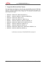
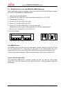
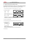
7.1 Power connector (X1)
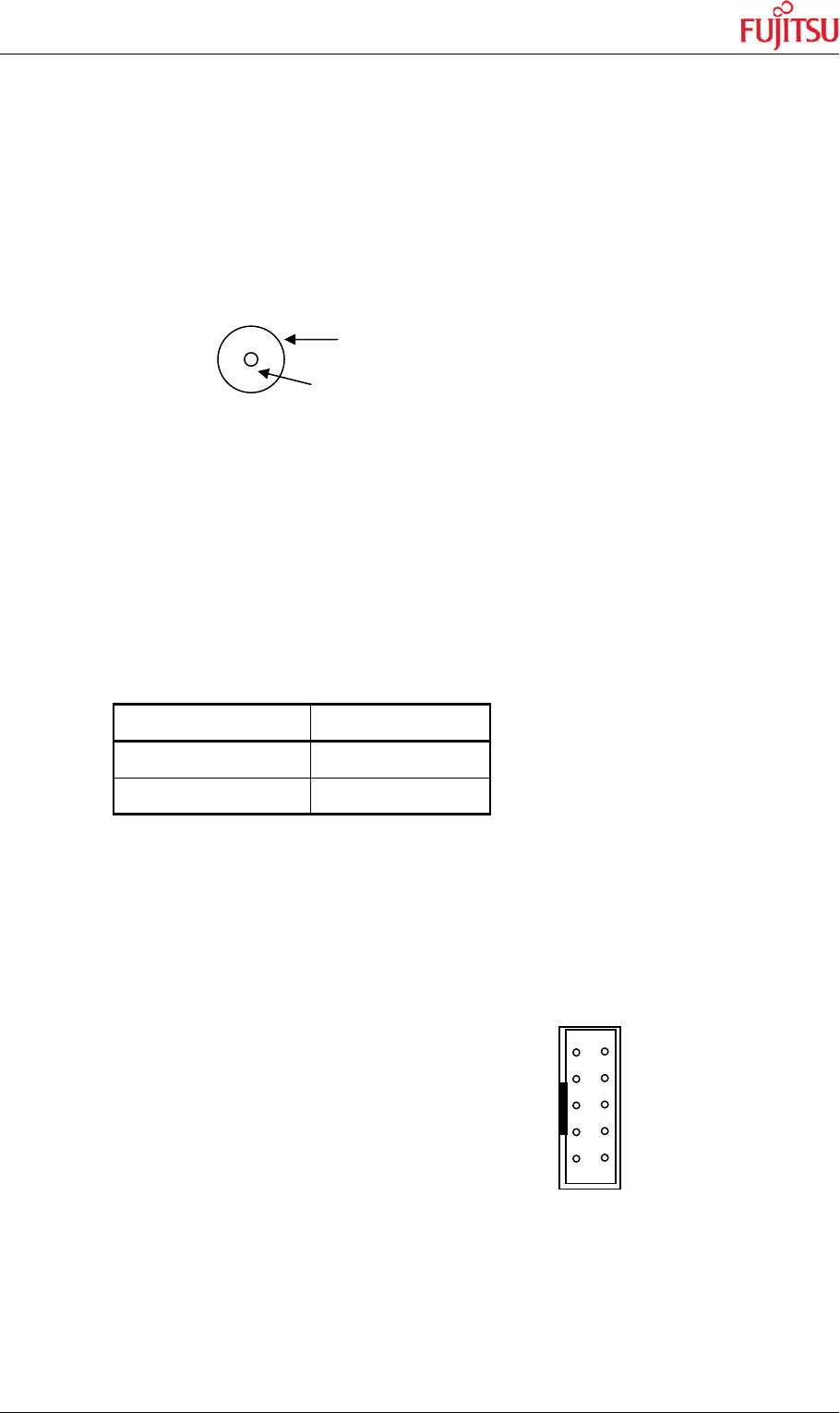
The following figure shows the power connection jack X1. This connector is used to connect
an external unregulated DC power supply voltage (9V-12V DC) to the evaluation board.
Connector X1:
It is recommended to use 9V to keep the power dissipation to a minimum. Otherwise, an
additional heat sink for the linear voltage regulator might be necessary.
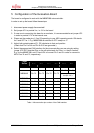
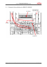
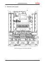
7.2 Edge connector (J2, J3, J4, J5)
All pins of the microcontroller (QFP-100 package) are directly connected to J2, J3, J4 and
J5, all are 2 x 25 Pin headers, as follows:
Connector MCU Pins
J2, J4 (1 – 50) 1 – 50
J3, J5 (51 – 100) 51 – 100
The odd pin numbers are located on the one side and the even pin numbers are located on
the other side of the connector.
On the PCB, the corresponding pin numbers of the TC are written next to the connector pins.
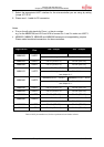
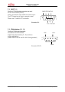
7.3 GND/VCC (JP11)
Additionally Vcc and GND Pins
are placed on the board (JP11).
Pinning of JP11
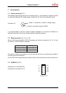
Shield is connected to positive voltage supply
Centre is connected to ground (GND)
Vcc 1
Vcc 3
Vcc 5
Vcc 7
Vcc 9
2 GND
4 GND
6 GND
8 GND
10 GND