


Change odd page title here
Chapter 5 Configuration of the Evaluation-Board
© Fujitsu Microelectronics Europe GmbH - 11 - UG-900001-32
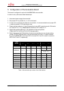
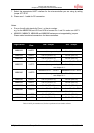
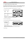
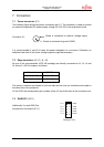
7. Select the appropriate UART interface for the microcontroller you are using by setting
jumper JP7-JP10.
8. Please use 1:1 cable for PC-connection.
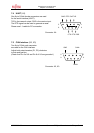
Notes:
< Pixx on the silk plot stands for Pinxx, i.e. the pin number.
e.g. for the MB90F598, set JP10 and JP9 to connect Pin 1 and 2 in order use UART 1
< MB90425, MB90470, MB90480 and MB90580 series are not supported by jumpers.
Please make handwired connections for these controllers.
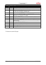
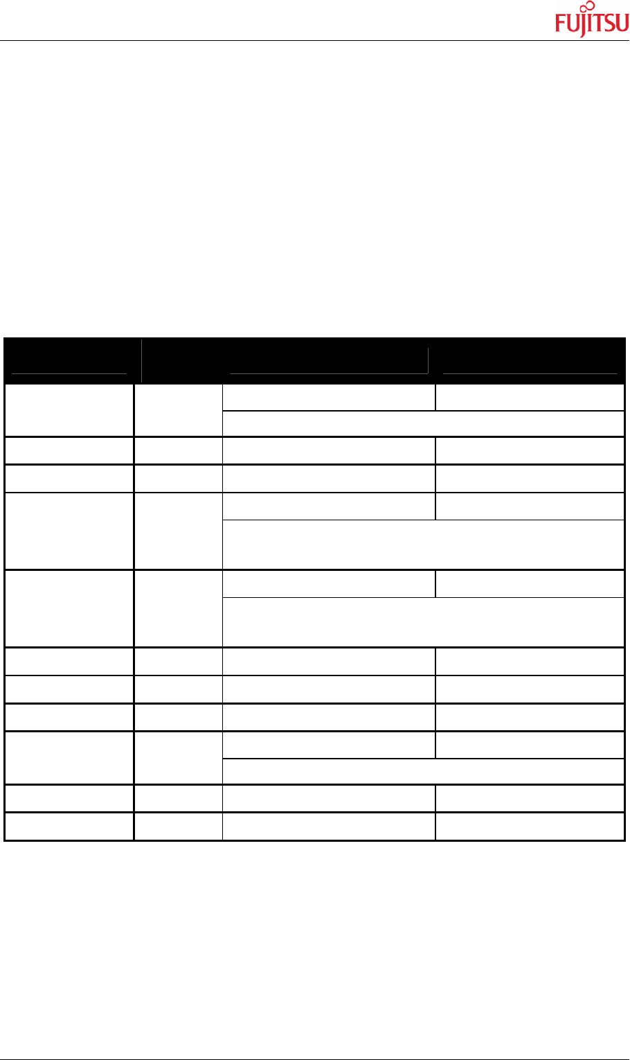
Target Series
Asynch.
Com.
SIN / Jumper SOT / Jumper
handwire Pin 88 – JP10.2 handwire Pin 89 – JP9.2
MB90425 UART1
(Not supported by Jumper JP7 - JP10)
MB90435 UART1 Pin 21 (JP10:1-2) Pin 24 (JP9:1-2)
MB90440 UART1 Pin 21 (JP10:1-2) Pin 24 (JP9:1-2)
handwire Pin 27 – JP10.2 handwire Pin 28 – JP9.2
MB90470 UART0
(Not supported by Jumper JP7 - JP10)
see chapter 6.1 !
handwire Pin 27 – JP10.2 handwire Pin 28 – JP9.2
MB90480 UART0
(Not supported by Jumper JP7 - JP10)
see chapter 6.1 !
MB90540 UART1 Pin 21 (JP10:1-2) Pin 24 (JP9:1-2)
MB90545 UART1 Pin 21 (JP10:1-2) Pin 24 (JP9:1-2)
MB90550 UART0 Pin 20 (JP8:1-2) Pin 19 (JP7:1-2)
handwire Pin 18 – JP10.2 handwire Pin 19 – JP9.2
MB90580 UART0
(Not supported by Jumper JP7 - JP10)
MB90590 UART0 Pin 16 (JP8:2-3) Pin 14 (JP7:2-3)
MB90595 UART1 Pin 21 (JP10:1-2) Pin 24 (JP9:1-2)
Table 2: MCU pin-number used, for the asynchronous boot-loader software