5
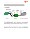
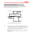
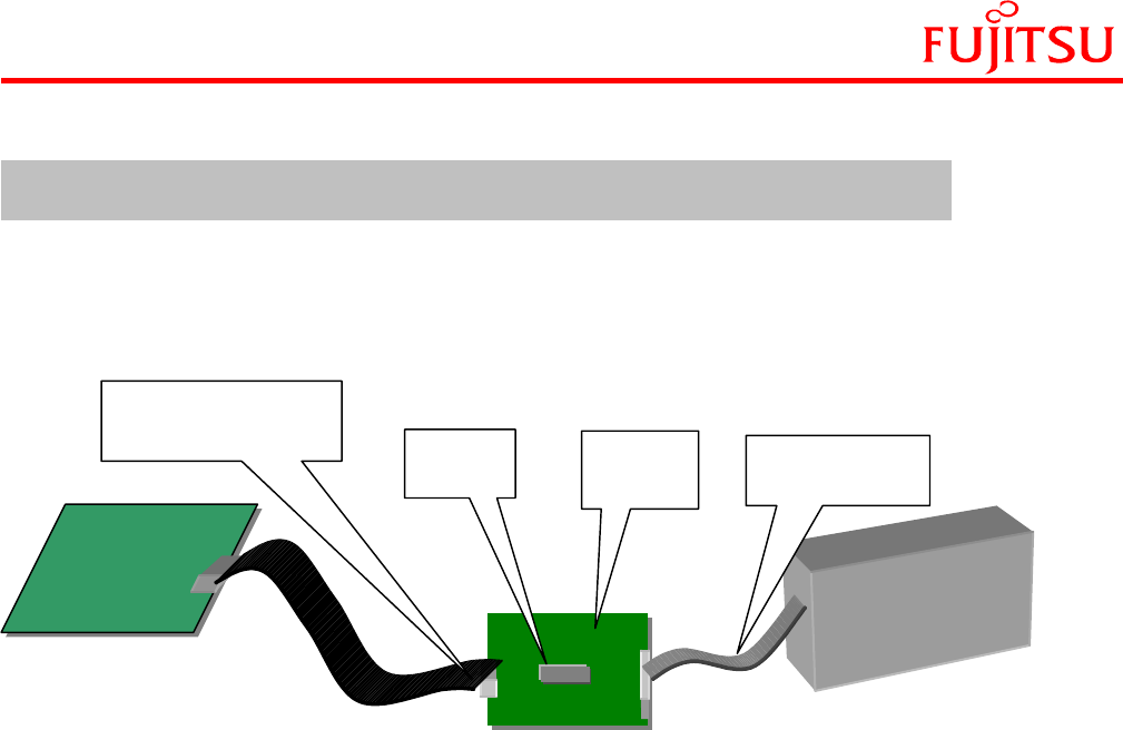
The diagram (figure1) below gives brief idea about all-necessary connections, which has to be done to program
the on chip Flash memory.
Target Board Adapter/Cable PC with Flash programming utility
Figure 1- Interface Diagram
Fujitsu standard Serial programming utility provides the asynchronous method to program the microcontroller.
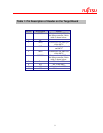
In order to connect the Microcontroller on board to the utility software, only the serial interface lines SOT
(Transmit) and SIN (Receive) are necessary. On the PC side to establish a connection to the Microcontroller the
RTS and CTS line should be connected together. The DTR should be connected to the DSR line in order to
avoid the communication error. The RD line has to be connected to the SOT, and the TD line has to be
connected to the SIN via the RS232 driver to the microcontroller for voltage level conversion.
The above whole connection requires the extra component such as RS232 driver and supporting components for
driver on target board. The adapter cable eliminates the above component requirement and provides the
complete solution. Hence no need of extra component on the user system for in circuit programming the Flash
Microcontroller.
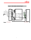
The Schematic of the adapter cable is shown in figure 2.
Adapter
Module
RS232
Drive
r
Serial Interface
Cable
Serial Interface of the Microcontroller to the PC via Cable
Serial cable or USB to
serial conversion cable


