9
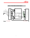
Pin No. Description Details
1 SIN/SI Connected to the SIN of
the Microcontroller. Refer
table-2 shown below.
2 NC
3 MD0 Connected to the MD0 pin
of the MCU
4 GND Ground of the Target board
and MCU
5 MD2 Connected to the MD2 pin
of the MCU
6 SOT/SO Connected to the SOT of
the Microcontroller. Refer
table-2 shown below.
7 Pxx P00 of the MCU
8 Pyy P01 of the MCU
9 +Vcc Supply to the MCU
10 NC -
Table 1: Pin Description of Header on the Target Board


