


8
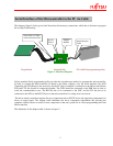
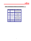
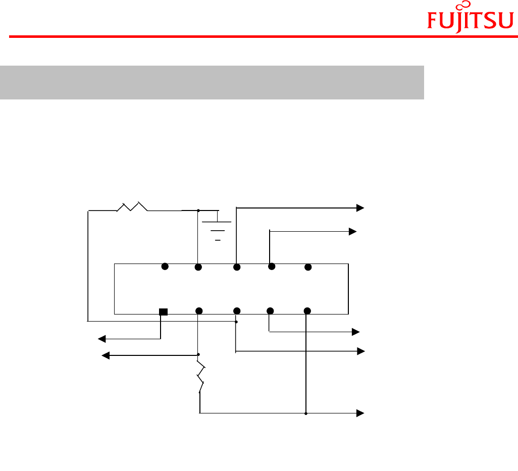
In order to connect the adapter cable to the target board, it is required to have the 10-pin standard IDC
header on the target board with the connection shown below. Figure 3 shows the connections from the
microcontroller to header. For detail pin out refer to Appendix A/B.
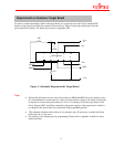
Note:
• Pull up and pull down resistor value shown above in MD0 and MD2 line is for reference only.
It is recommended to connect the low value of pull up resistor (Approx 470 ohm) to mode pins
if required or connect these pins directly to Vcc or Vss directly as per the logic shown in the
above diagram. MD1 should be connected to the power supply on the target board, as there is
no change in the signal status for normal and flash-programming mode.
• The schematic diagram shown above is for reference only. If necessary, consider the 10-pin
header pin out as a top view.
• Pxx and Pyy is the starting pin for programming. Please refer to appendix A and B for more
detail about this.
Figure 3: Schematic Diagram on the Target Board
47K
470
2 4 6 8 10
1 3 5 7 9
Pyy
SOT/
SO
Pxx
MD2
+Vcc
MD0
SIN/SI
GND
10 Pin Header
Requirement on Customer Target Board