


3-6 C141-E166
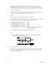
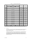
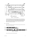
n = 241 (zone 0) ~ 408 (zone 17)
5.99 msec
Servo frame
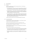
Figure 3.4 Track format
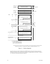
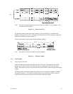
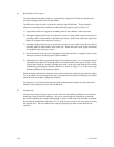
(2) Track skew and head skew
To avoid waiting for one turn involved in head and cylinder switching, the first logical data block
in each track is shifted by the number of sectors (track skew and head skew) corresponding to the
switching time. Figure 3.5 shows how the data block is allocated in each track.
At the head switching location in a cylinder, the first logical data block in track t + 1 is allocated at
the sector position which locates the track skew behind the sector position of the last logical data
block sector in track t.
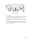
At the cylinder switching location, like the head switching location, the first logical data block in a
cylinder is allocated at the sector position which locates the head skew behind the last logical
sector position in the preceding cylinder. The last logical sector in the cylinder is allocated when
formatting, and is an unused spare sector.