


4-14 C141-E166
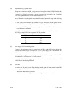
Pin 1
Pin 34
Pin 68
Pin 35
2.00m
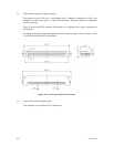
Pin A1
Pin A2
Pin 1
2.54mm
5.08mm
1.30mm
2.00mm
5.08mm
1.27mm
0.40mm
0.635mm
0.40mm
1.00mm
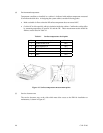
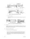
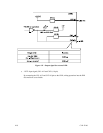
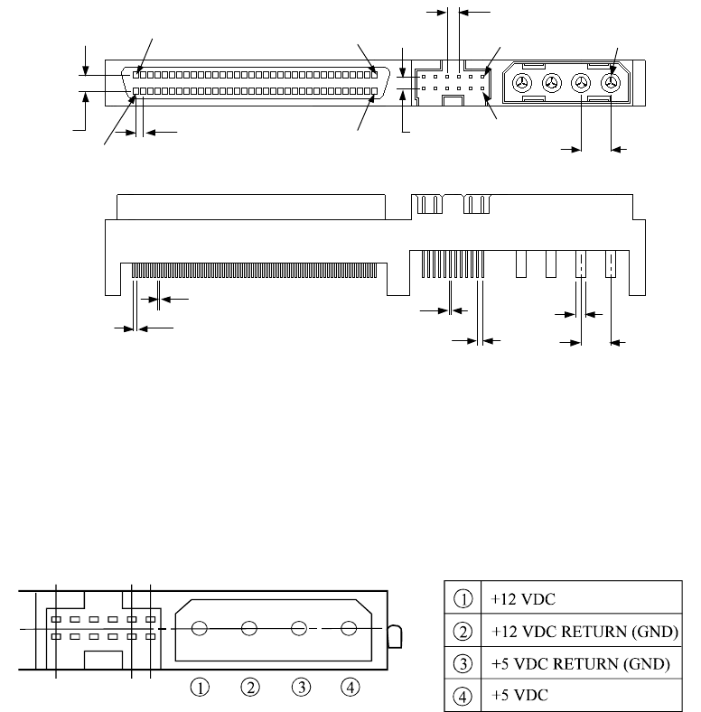
Figure 4.16 68 pin type 16-bit SCSI interface connector
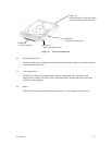
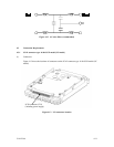
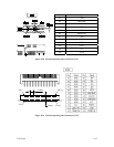
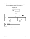
b. Power supply connector
Figure 4.17 shows the shape and the terminal arrangement of the output connector of DC
power supply.
Figure 4.17 Power supply connector (68 pin type 16-bit SCSI)
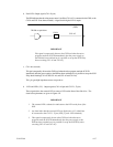
(3) SG terminal
The IDD is not provided with an SG terminal (fasten tab) for DC grounding. Therefore, when
connecting SG and FG in the system, use the +5 VDC RETURN (ground) inside the power supply
connector as the SG on the power supply side.
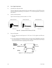
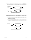
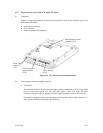
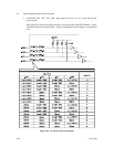
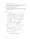
(4) Connector for external operator panel
• Connector for 16-bit SCSI external operator panel
CN1 provides connector for the external operator panel other than the SCSI bus as shown in
Figure 4.18. Also, a connector for the external operator panel are provided on the IDD as
shown in Figure 4.19. This allows connection of an external LED on the front panel, and an
SCSI ID setting switch. For the recommended circuit of the external operator panel, see
Subsection 4.3.4.