


C141-E166 4-21
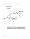
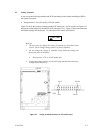
(4) External operator panel (NP model only)
The external operator panel is installed only when required for the system. When connection is not
required, leave open the following pins in the external operator panel connector of the IDD : Pins
21, 22 and pins 01 through 08 in CN2 and pins A1 through A12 in CN1.
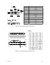
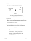
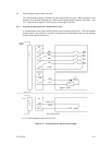
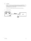
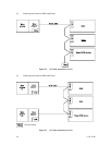
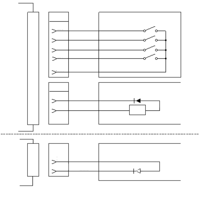
4.3.4 External operator panel (on NP model drives only)
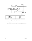
A recommended circuit of the external operator panel is shown in Figure 4.23. Since the external
operator panel is not provided as an option, this panel must be fabricated at the user site referring
to the recommendation if necessary.
(IDD)
C
N
1
S3
A1
A3
A5
A7
A10
-ID0
-ID1
-ID2
-ID3
GND
ID0
ID1
ID2
ID3
S3
A8
A11
-LED
+5V
(LED)
R
Approx. 300
Ω
(*1)
C
N
2
S4
21
22
LED (+5V)
-LED
(LED)
(for 16-bit SCSI)
(*1) For connecting the external LED to CN2.
Figure 4.23 External operator panel circuit example