Data Format
3-2 C141-E163
Note
:
Spare sectors on the last track in each cylinder are not necessarily placed at the end of the track
because of a track skew or a cylinder skew. (Details are explained in Subsection 3.1.3.)
n = MAP3147FC: 47,925
MAP3735FC: 47,995
Zone Cell Cylinder
Cylinder –73
to
Cylinder –4
System space
Internal test space
Cylinder –85
to
Cylinder –78
•
SA0
SAS69
Internal test cylinder
~~
~~
~~
~~
Spare Sectors per Cell 0
0
01
•
13
User Space for Cell 0-0
Spare Sectors per Cell 1
14
115
•
0 27
•
User Space for Cell 1-0
m-13
P1
•
m
User Space for Cell P1-0
Spare Sectors per Cell P1
Alternate Cylinder
User Space for Cell xx-1
User Space for Cell yy-17
User Space
(Primary Cylinder
0 - (n-1))
(1)
1
17 n
:
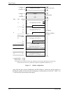
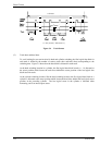
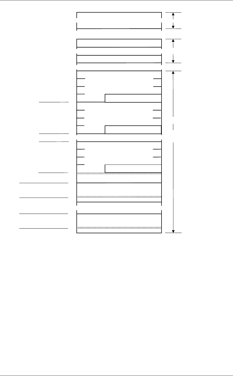
Figure 3.1 Cylinder configuration
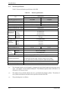
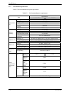
Apart from the above logical configuration, the IDD intends to increase the storage capacity by
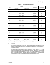
dividing all cylinders into several zones and changing a recording density of each zone. Tables 3.1 to
3.3 show the zone layout and the track capacity.


