


C141-E226 3-5
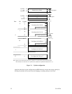
3.1.3 Track format
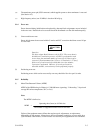
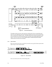
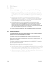
(1) Physical sector allocation
Figure 3.4 shows the allocation of the physical sectors in a track. The length in bytes of each
physical sector and the number of sectors per track vary depending on the logical data block
length. The unused area (G4) exists at the end of the track in formats with most logical data block
lengths.
The interval of the sector pulse (length of the physical sector) is decided by the HDD internal free
running clock frequency. This clock is not equal to the interval of the byte clock for each zone.
Therefore, the physical sector length cannot be described with a byte length.
Servo frame
Figure 3.4 Track format
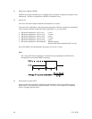
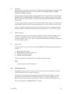
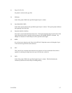
(2) Track skew and head skew
To avoid waiting for one turn involved in head and cylinder switching, the first logical data block
in each track is shifted by the number of sectors (track skew and head skew) corresponding to the
switching time. Figure 3.5 shows how the data block is allocated in each track.
At the cylinder switching location in a head, the first logical data block in track t + 1 is allocated at
the sector position which locates the track skew behind the sector position of the last logical data
block sector in track t.
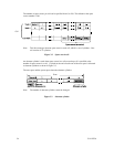
At the head switching location, like the cylinder switching location, the first logical data block in a
head is allocated at the sector position which locates the head skew behind the last logical sector
position in the preceding head. The last logical sector in the cell is allocated when formatting, and
is an unused spare sector.