


C141-E226 5-5
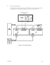
5.3 Setting Terminals
A user sets up the following terminals and SCSI terminating resistor before installing the HDD in
the system as required.
• Setting terminal: CN1 (NC model), CN2 (NP model)
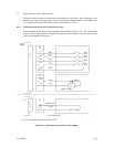
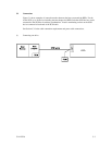
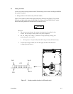
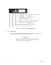
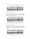
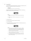
Figure 5.2 shows the location of the setting terminal for NP model, and Figure 5.3 shows the
allocation and the default settings for NP model. See Figure 4.13 and Table B for NC model
because the setting terminal is included in SCSI connector (CN1).
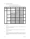
CAUTION
Data loss
1. The user must not change the setting of terminals not described in this
section. Do not change setting status set at factory shipment.
2. Do not change the setting of terminals except following setting pins
during the power is turned on.
• Write protect: Pin pair 9/10 of the CN2 setting terminal (NP model only)
3. To short the setting terminal, use the short plug attached when the device
is shipped from the factory.
Pin 1
Pin 23
Pin 24
CN2
Pin 2
Figure 5.2 Setting terminals location (on NP models only)