


Host Interface
4-4 C156-E227-01EN
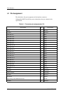
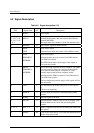
4.2 Signal Description
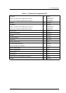
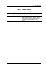
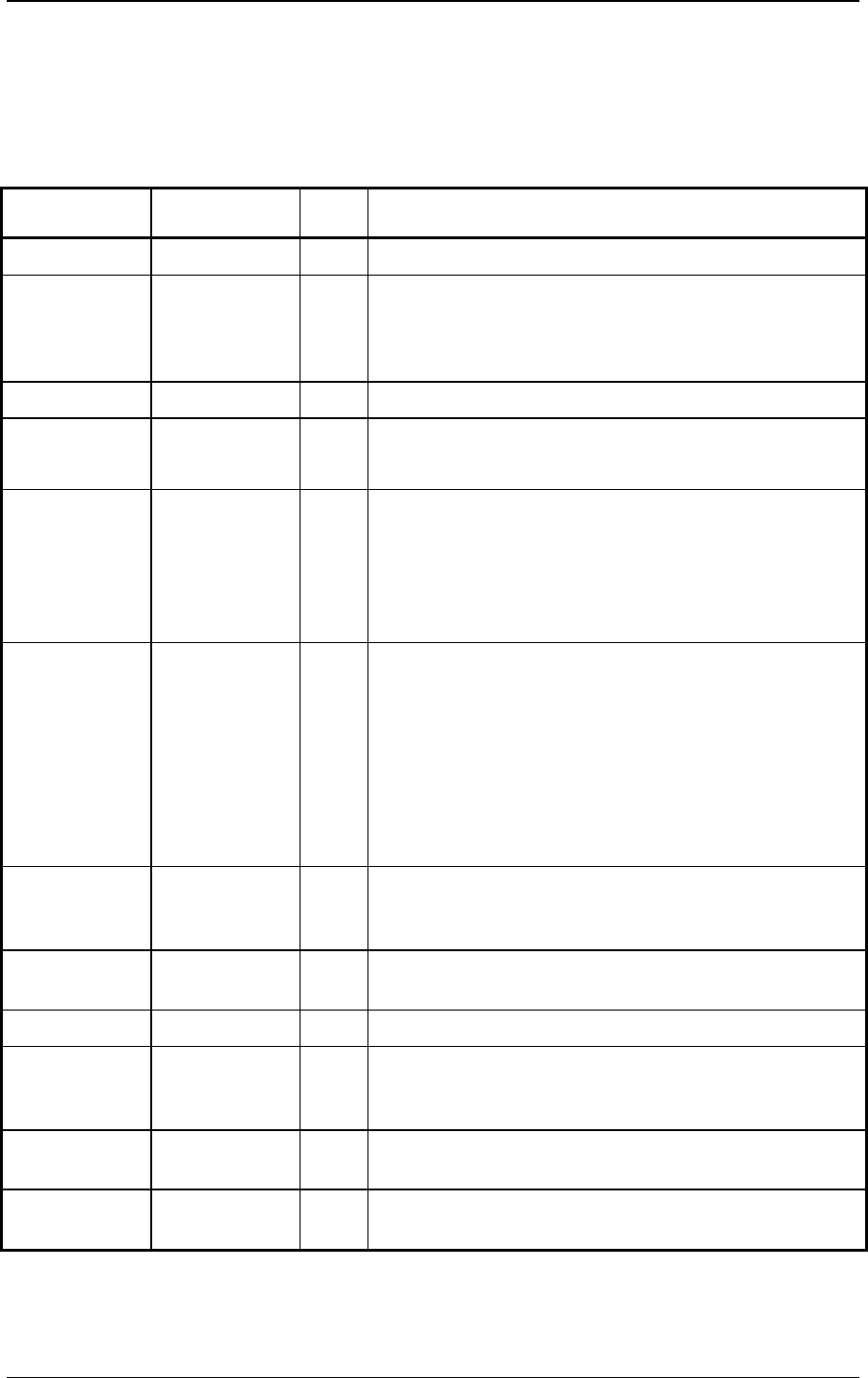
Table 4.2 Signal description (1/2)
PIN Signal name I/O Description
1 RESET- I Reset signal
3, 5, 7, 9, 11,
13, 15, 17, 18,
16, 14, 12, 10,
8, 6, 4
DD7-0
DD15-8
I/O The low-order bus is a 8-bit bidirectional bus signal for
exchanging the status, data, and control data between
the host and ODD.
The high-order bus is used for 16-bit data transfers only.
21 DMARQ O Data request signal for DMA transfer
23 DIOW-
STOP
I Write strobe signal.
Indicates that transfer has ended at Ultra DMA transfer.
25 DIOR-
HDMARDY-
HSTROBE
I Read strobe signal
Indicates that the host can receive Ultra DMA data at
Ultra DMA in transfer.
The ODD latches data at both edges of this signal at
Ultra data out transfer.
27 IORDY
DDMARDY-
DSTROBE
O This is the ready signal for the host computer. The ODD
uses this signal to request an extension of the transfer
cycle when it cannot prepare a response to a data
transfer request from the host computer in time.
Indicates that the ODD can receive Ultra DMA data at
Ultra DMA out transfer.
The host latches data at both edges of this signal at Ultra
data in transfer.
28 CSEL I Sets the ODD to the master (device 0) or slave (device
1).
Effective by jumpering.
29 DMACK- I Answer signal in response to DMARQ during DMA
transfer
31 INTRQ O Interrupt signal to the host
32 IOCS16- O Indicates that the ODD is ready for 16-bit transfer when
the host addresses the 16-bit data port during PIO
transfer.
36, 33, 35 DA2, 1, 0 O Address signal used by the host to address the ODD task
file register
34 PDIAG- I/O Used by the slave (device 1) to notify the master (device
0) that diagnostics ended