


Interface
5-90 C141-E224
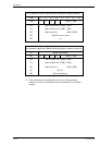
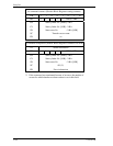
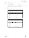
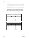
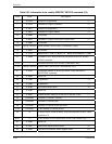
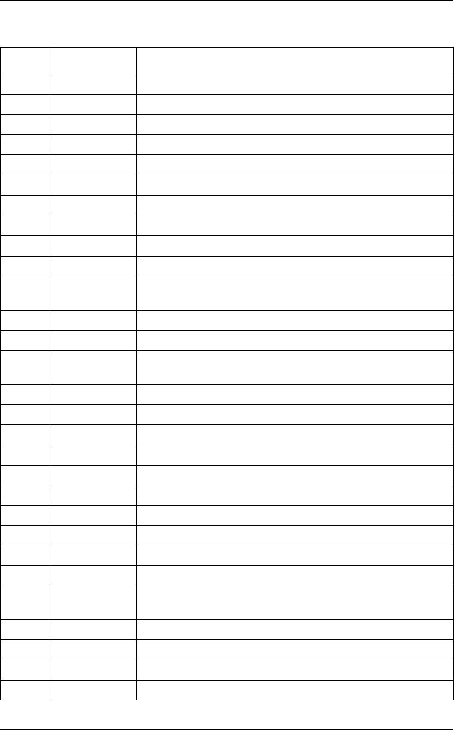
Table 5.25 Information to be read by IDENTIFY DEVICE command (1/3)
Word Value Description
0 X’045A’ General Configuration *1
1 X’3FFF’ Number of Logical cylinders *2
2 X’C837’ Detailed Configuration *3
3 X’0010’ Number of Logical Heads *2
4-5 X’0000’ Undefined
6 X’003F’ Number of Logical sectors per Logical track *2
7-9 X’0000’ Undefined
10-19 Set by a device Serial number (ASCII code, 20 characters, right)
20 X’0003’ Undefined
21 X’xxxx’ Buffer Size (1 LSB: 512 Bytes) ex. Buffer Size=8MBytes: X’4000’
22 X’0004’ Number of ECC bytes transferred at READ LONG or WRITE
LONG command
23-26 – Firmware revision (ASCII code, 8 characters, left)
27-46 Set by a device Model name (ASCII code, 40 characters, left)
47 X’8010’ Maximum number of sectors per block on READ/WRITE
MULTIPLE command
48 X’0000’ Reserved
49 X’2F00’ Capabilities *4
50 X’4000’ Capabilities *5
51 X’0200’ PIO data transfer mode *6
52 X’0200’ Reserved
53 X’0007’ Enable/disable setting of words 54-58 and 64-70, 88 *7
54 (Variable) Number of current Cylinders
55 (Variable) Number of current Head
56 (Variable) Number of current sectors per track
57-58 (Variable) Total number of current sectors
59 *8 Transfer sector count currently set by READ/WRITE MULTIPLE
command *8
60-61 *2 Total number of user addressable sectors (LBA mode only) *2
62 X’0000’ Reserved
63 X’xx07’ Multiword DMA transfer mode *9
64 X’0003’ Advance PIO transfer mode support status *10