


Installation Conditions
3-10 C141-E224
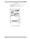
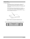
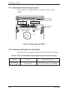
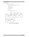
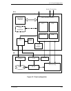
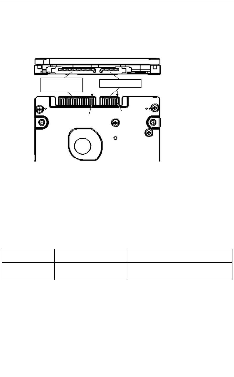
3.3.2 Signal segment and power supply segment
Figure 3.9 shows each segment of the SATA interface connector and pin
numbers.
Power suppl
y
segment
P1 pins in the power
supply segment
S1 pins in the si
g
nal
segment
View from the
connector side
View from the
PCA side
Si
g
nal se
g
ment
Figure 3.9 Power supply pins (CN1)
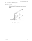
3.3.3 Connector specifications for host system
Table 3.2 lists the recommended specifications for the host interface connectors.
Table 3.2 The recommended connector specifications for the host system
Segment Name Model (Manufacturer)
SATA interface
and power supply
Host receptacle 67492-0220 (Molex) or compatibles