


C141-E112-01EN
4 - 1
CHAPTER 4 THEORY OF DEVICE OPERATION
4.1 Outline
4.2 Subassemblies
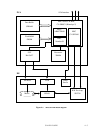
4.3 Circuit Configuration
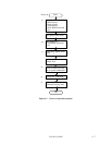
4.4 Power-on sequence
4.5 Self-calibration
4.6 Read/write Circuit
4.7 Servo Control
This chapter explains basic design concepts of the disk drive. Also, this chapter explains subassemblies of
the disk drive, each sequence, servo control, and electrical circuit blocks.
4.1 Outline
This chapter consists of two parts. First part (Section 4.2) explains mechanical assemblies of the
disk drive. Second part (Sections 4.3 through 4.7) explains a servo information recorded in the
disk drive and drive control method.
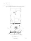
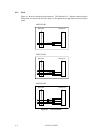
4.2 Subassemblies
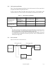
The disk drive consists of a disk enclosure (DE) and printed circuit assembly (PCA).
The DE contains all movable parts in the disk drive, including the disk, spindle, actuator,
read/write head, and air filter. For details, see Subsections 4.2.1 to 4.2.5.
The PCA contains the control circuits for the disk drive. The disk drive has one PCA. For details,
see Sections 4.3.
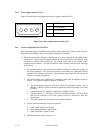
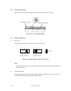
4.2.1 Disk
The DE contains the disks with an outer diameter of 95 mm. The MPG3102AH has 1 disk, and
MPG3153AH and MPG3204AH have 2 disk.
The head contacts the disk each time the disk rotation stops; the life of the disk is 50,000 contacts
or more.
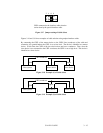
Servo data is recorded on each cylinder (total 96). Servo data written at factory is read out by the
read/write head. For servo data, see Section 4.7.