


C141-E112-01EN
4 - 12
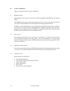
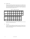
4.6.4 Synthesizer circuit
The drive uses constant density recording to increase total capacity. This is different from the
conventional method of recording data with a fixed data transfer rate at all data area. In the
constant density recording method, data area is divided into zones by radius and the data transfer
rate is set so that the recording density of the inner cylinder of each zone is nearly constant. The
drive divides data area into 15 zones to set the data transfer rate. Table 4.1 describes the data
transfer rate and recording density (BPI) of each zone.
Table 4.1 Transfer rate of each zone
Zone 01234567
Cylinder 0
to
1215
1216
to
2431
2432
to
3743
3744
to
4831
4832
to
5823
5824
to
7743
7744
to
9631
9632
to
10815
Transfer rate
[MB/s]
50.82 50.82 50.82 50.20 49.41 47.45 45.49 43.92
Zone 8 9 10 11 12 13 14
Cylinder 10816
to
12351
12352
to
13951
13952
to
15231
15232
to
16287
16288
to
17823
17824
to
19071
19072
to
19423
Transfer rate
[MB/s]
41.76 39.53 37.65 36.08 33.73 31.76 29.65
The MPU transfers the data transfer rate setup data to the RDC that includes the time base
generator circuit to change the data transfer rate.
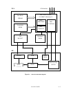
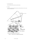
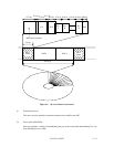
4.7 Servo Control
The actuator motor and the spindle motor are submitted to servo control. The actuator motor is
controlled for moving and positioning the head to the track containing the desired data. To turn
the disk at a constant velocity, the actuator motor is controlled according to the servo data that is
written on the data side beforehand.