


C141-E112-01EN
4 - 17
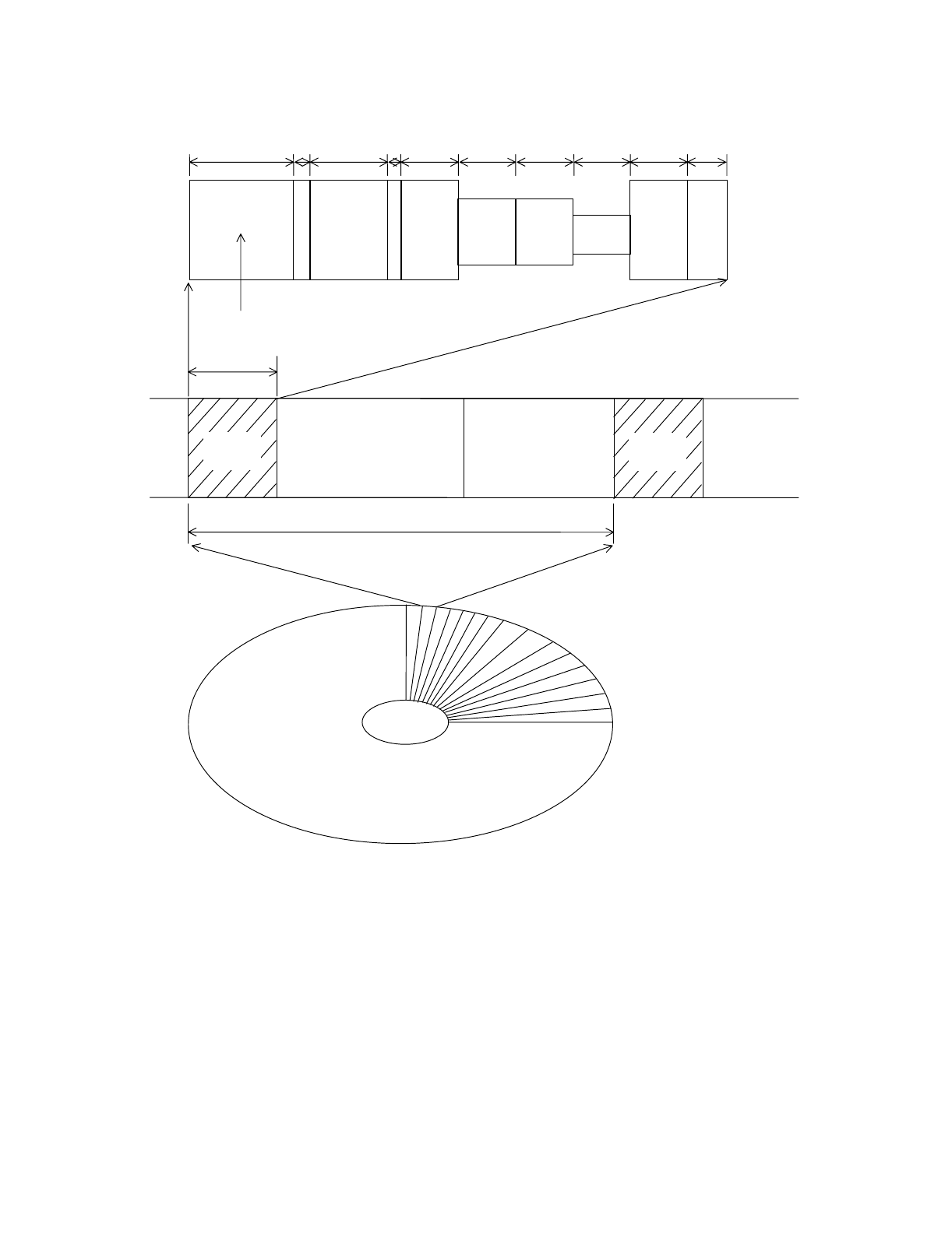
Pos
C
PAD
Pos
D
Pos
B
Pos
A
1.81 µs
0.17 µs
0.16 µs
0.72 µs
R/W Recovery Field
0.56 µs
0.56 µs0.56 µs0.74 µs
0.80 µs
PA
SSMASM
SCD
0.53 µs
Servo
Frame
DATA DATA
Servo
Frame
86.81 µs
6.63 µs
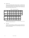
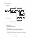
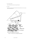
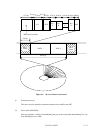
Figure 4.6 96 servo frames in each track
(1) Write/read recovery
This area is used to absorb the write/read transient and to stabilize the AGC.
(2) Servo mark (ASM, SSM)
This area generates a timing for demodulating the gray code and position-demodulating Pos A to
D by detecting the servo mark.