1. OPERATIONAL OVERVIEW
1-14
1.4.6 Suitable tilt angle
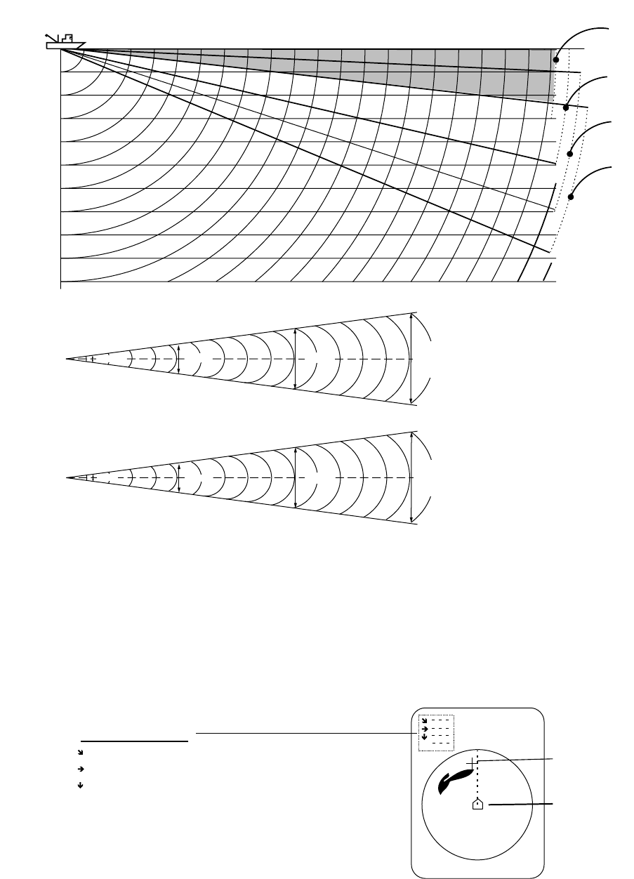
The table below shows the estimated detection range for tilt angles of 0, 5, 10
and 15 degrees. Refer to the table to find suitable tilt angle from depth and
detection range.
Vertical width of sonar beam
Depth (m)
100
(200)
200
(400)
300
(600)
400
(800)
0°
5°
10°
15°
20(40)
40(80)
60(120)
80(160)
100(200)
200(400)
100 m
300 m
78 m
200 m
Detection range (m)
CSH-5L
13°
23 m
100 m
300 m
68 m
200 m
46 m
CSH-8L
Tilt angle setting
52 m
26 m
15°
Depth, detection range and tilt angle
1.5 Finding Range and Bearing to a Target
Operate the trackball to place the trackball mark on the target you want to
measure the range and bearing. The slant range, horizontal range, bearing and
depth to the target appear at the upper left corner of the sonar display.
B
Trackball mark
TRACKBALL DATA
Slant range from own ship to trackball mark
Horizontal range from own ship to trackball mark
Depth to trackball mark
B Relative from own ship to trackball mark*
* = Relative bearing format may be selected with
OTHER MARKS on the MARKS menu.
Own ship mark
Location of trackball data


