


A
P-1
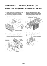
APPENDIX REPLACEMENT OF
PRINTER ASSEMBLY/TERMAL HEAD
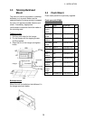
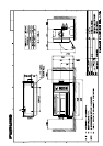
1. Loosen the four M4 × 15 screws fixing the
rear cabinet to the main unit assembly.
2. Disconnect the connectors connected to
the rear cabinet to detach the rear
cabinet.
Rear
Cabinet
Main Unit Assembly
P1
NH
4P
P5
NH
6P
M4 × 15
screw
(4 pcs.)
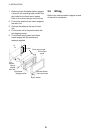
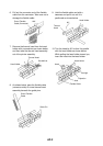
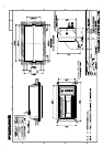
3. Separate the panel assembly from the
main unit assembly by removing the
recording paper from the paper container.
Main Unit
Assembly
Printer
Assembly
PANEL CPU Board
Do not
Disconnect.
Panel
Assembly
P4
PH
12P
P8
PH
10P
P10
PH12P
M4 × 8
screw
(4 pcs.)
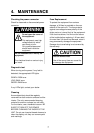
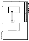
4. Move the carriage to position
A
by
rotating the carriage shaft by fingers, as
shown below, where the thermal head
assembly can be replaced easily.
Carriage Shaft
Carriage
A
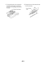
5. Remove the flexible cable support from
the carriage by lifting it toward direction
B
as in the figure below.
Flexible Cable Support
Carriage