


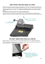
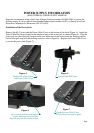


Attach the supplied tie wrap anchors to the
underside of the dock by pushing into the holes in
the locations shown (Figure 3).
Attach cable ties to the anchors as shown (Figure
3).
Retain the USB and Ethernet cables at the
Restraint Bracket using the supplied cable ties
(Figure 3). If the USB or Ethernet cables do not fit
with the Restraint Bracket, remove the bracket and
restrain the cables with the additional tie wrap
anchors supplied in the hardware bag.
Figure 3
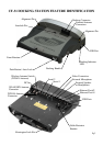
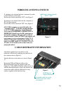
If wanting to use external antenna, connected by cable
to the WAN port on the dock:
Position the switch toward the "EXT" side (Figure 2).
If wanting to use antenna built into the computer or a
PC Card type antenna:
Position the switch toward the "INT" side (Figure 2).
CF-31 MK1 computers are not effected by the
"Antenna Switch". To disable external antenna use
on all CF31-MK1 computers, install Panasonic
service part # [DFHR3S40ZA, DFHR3S39ZA or
DFHR3S38ZA(dual)] over the RF connection on the
back of the computer. This part can be ordered
from Panasonic (1-800-LAPTOP5) and support will
send request to service department. If the CF-31
Model # is followed by the following Alpha's you
know it is a MK1 model: CF-32A, B/E, C, D or G.
All other CF-31 models work as state in the two
paragraphs above.
Pg 5
WIRELESS ANTENNA SWITCH
CABLE RESTRAINT INFORMATION
Figure 2
USB/Ethernet
Support Bracket
Assemble cable ties to the
anchors and route cables
as required.
Wireless Antenna Switch
"EXT" / "INT"