


Magnum DS50 / DS60s Dual Speed Hubs Installation and User Guide (06/02)
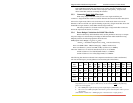
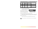
Each Fast Ethernet device component also has an associated BT delay, which
depends on the physical signaling system employed. Table 3.2b shows each Fast Ethernet
device component and the associated BT delay. Note that there is only one DTE pair
associated with any device-to-device path.
Table 3.2b: Worst case round-trip delay for Fast Ethernet device components*
Component Round-trip delay in Bit Times (BT)
2 TX DTEs
100
2 FX DTEs
100
1 FX and 1 TX DTE
100
2 T4 DTEs
138
1 T4 and 1 TX or FX DTE
127
Class I Repeater
140
Class II Repeater with any
combination of TX and FX ports
92
**Note, the delay is only 80 Bit Times
for the MagnumDS50 / DS60, ports 1-5.
*Worst case delays taken from IEEE Std 802.3u-1995.
To determine whether a prospective network topology adheres to the collision
domain diameter specification, the following formula should be applied to the worst case path
through the network. The worst case path is the path between the two Fast Ethernet devices
(DTEs) which have the longest round trip time.
PDV = (sum of cabling delays) + (sum of repeater delays) +
(DTE pair delay) + (safety margin)
PDV is the Path Delay Value of the worst case path. For the network to adhere to
IEEE standard, this value must be less than 512 BT. The safety margin is specified in BT and
may be a value between 0 and 5. This margin can be used to accommodate unexpected delays,
as seen when using extra long patch cables. A safety margin from about 2 to 4 BT is
recommended.
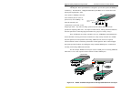
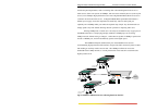
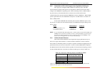
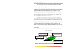
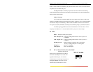
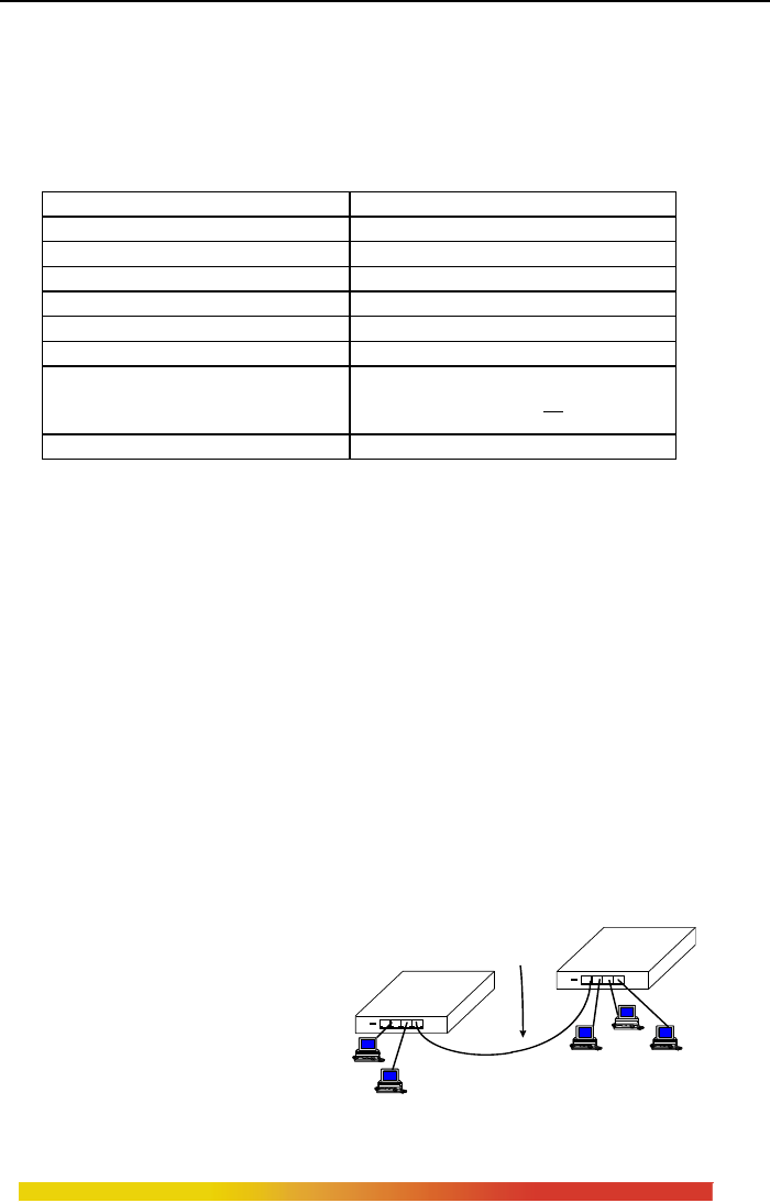
A typical example of a
PDV calculation is shown to the
right. The example is illustrated in
Figure 3.2a. Here, an integrator
wishes to cascade two industry-
standard Fast Ethernet hubs with
100m Category 5 user segments
(i.e., from computer to hub) and
LINK
RX
PWRCOL
LINK
RX
PWRCOL
100 m cat. 5 cables
to user devices
Cat. 5 cable for
cascading
Industry-
Standard
100Mb/s Hub
Industry-
Standard
100Mb/s Hub
23
www GarrettCom com
..