


Magnum 500-Series Switching Hubs Installation and User Guide (08/98)
GARRETT
14
3.0 INSTALLATION
This chapter provides instructions for installing Magnum 500-Series switches.
3.1 Locating Magnum 500-Series switches
The location of a Magnum 500-Series switch is dependent on the physical
layout of the network. Typically the switch is placed where combinations of 10Mb and
100Mb network devices need to be connected to communicate with each other. The
compact size of the unit allows it to be conveniently placed in an office or lab area, and it
can also be either shelf of wall-mounted (see instructions in 3.1.2 below). Wall-
mounting brackets are included, usable for single units (but not for stacks).
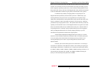
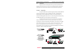
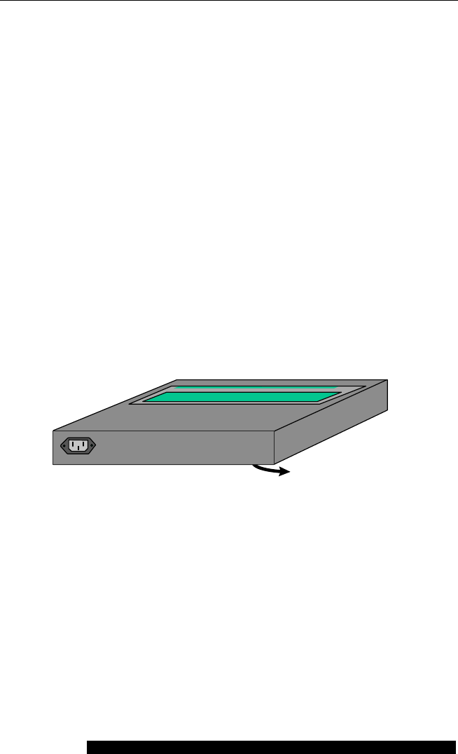
Locate an AC receptacle that is within six feet (2 meters) of the intended
Magnum 500 site. The rugged metal case of the Magnum 500 will normally protect it
from accidental damage in a lab or workplace setting. Maintain an open view of the front
to visually monitor the status LEDs. Keep an open area around the unit so that cooling
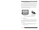
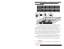
can occur from the small fan in the bottom-rear while the unit is in operation. See figure
below.
Figure 3.1 : Location of Magnum 500’s cooling fan exhaust
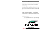
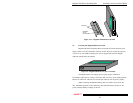
3.1.1 Table-Top or Shelf Mounting
The Magnum 500-Series switch can be easily mounted on a table-top or any
suitable horizontal surface, and has four rubber feet to provide stability without
scratching finished surfaces. When stacked, the rubber feet also provide separation
between units for the exhaust of the rear cooling fan.
GARRETT
115-230V~ 50/60 Hz
FAN EXHAUST