


Magnum 500-Series Switching Hubs Installation and User Guide (08/98)
GARRETT
15
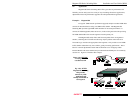
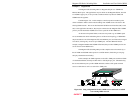
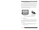
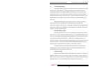
3.1.2 Wall (or Vertical Surface) Mounting
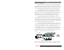
Each Magnum 500-Series switch is shipped with two metal mounting brackets
(and screws) to allow the unit to be mounted in nearly any desired orientation or position.
The brackets are attached to the metal hub case using one of the metal screws for each
bracket, and attached to the Magnum 500 through the round hole of the bracket. A user-
supplied screw attaches the bracket to the mounting surface. It is recommended that the
mounting brackets be attached to two opposite corners of the unit. When properly
attached, the brackets will extend slightly below the base of the unit to allow clearance
for the rubber feet and for cooling fan exhaust space.
Figure 3.1: Magnum 500-Series, metal mounting brackets
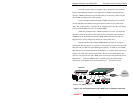
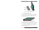
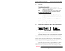
3.1.3 Optional E-Stand
The optional E-Stand provides a vertical mounting option for the Magnum
500-Series Hubs. When horizontal placement is not possible or desirable (such as on the
floor in carpeted areas), the E-Stand offers a unique space management option. Simply
align the rectangular cut-out on the E-Stand with the air vent on either side of the
Magnum 500 unit.
The E-Stand also allows the Magnum 500-Series unit to be securely mounted
via two screws that connect through the E-Stand and into the side of the unit.
See Figure 3.1.3, following.
Ma
g
num 500 with attached
mountin
g
brackets
GARRETT
Magnum 500
-
series
Switchin
g
Hub
Pro
p
er mountin
g
bracket attachment
GARRETT
100 Mb/s
AU
TO
F/
H
PW
R
LK/RX
F
D
X
1
0
0
1
0