Magnum 500-Series Switching Hubs Installation and User Guide (08/98)
GARRETT
21
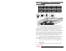
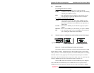
4.2 Status LEDs
For all Magnum 500-series models :
PWR :
Power LED, ON when AC power is applied to the unit.
LK/RX :
Link/Receive LED per 10Mb port, Steady ON for Link, Flashing
when the port has Receive activity.
FDX :
Full / Half Duplex LED per 10Mb port, ON when the port has
auto-negotiated to operate Full Duplex, OFF for half duplex.
For Magnum 528 and 528F models only :
AUTO :
Auto-negotiation LED, ON when copper “100Mb” ports are
configured to operate in the auto-negotiation mode, OFF when
their speed is internally fixed at 100Mb (no auto-negotiation, no
10Mb speed).
10 LED :
One for each “100Mb” port, ON when the copper port speed is
10Mb/s.
100 LED :
One for each “100Mb” port, ON when the port speed is 100Mb/s.
F/H :
Full / Half duplex LED, one for each 100Mb port, ON when the
port is running full duplex, OFF for half duplex.
4.3
Manual switches for 10Mb Up-link, and Fast Ethernet Full / Half Duplex
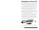
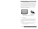
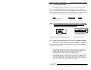
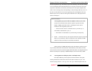
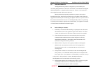
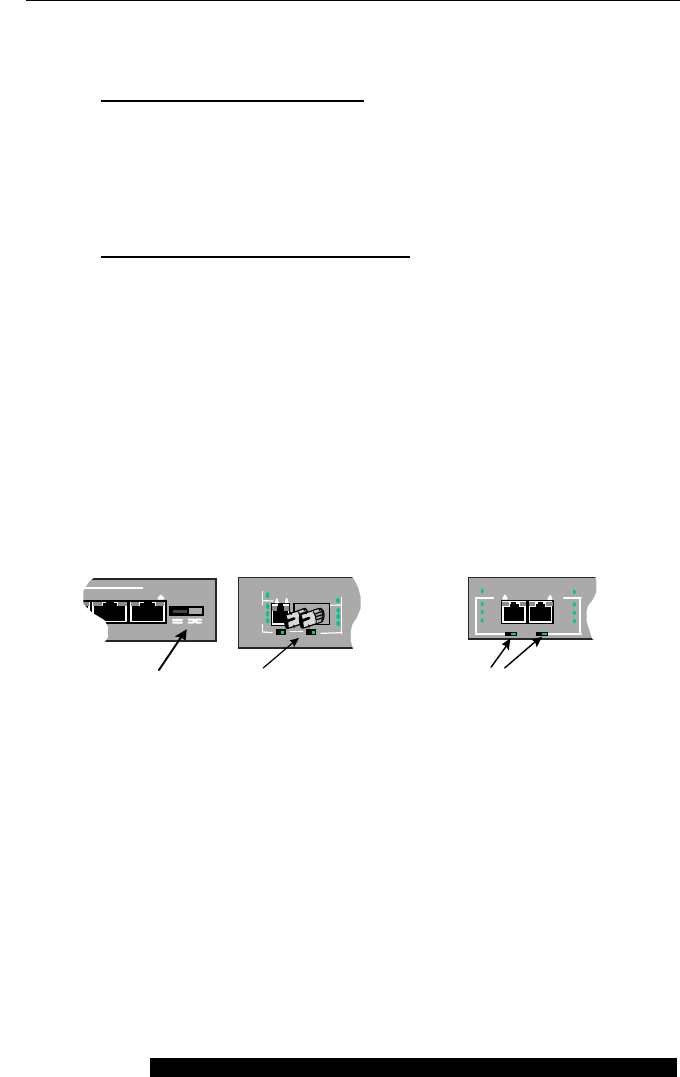
Figure 4.3 : Up-link and F/H manual switches on front panel
The unit has a manual Up-link switch, located on the front panel next to 10Mb
Port # 8 which it controls. It enables the port’s cable to either connect to a user station
node (= position) or to be cascaded (X position) to a another 10Mb repeater or switching
hub in the network. Verify proper Up-link switch position by noting Port 8’s LK/RX
LED status, which is illuminated when a proper link is made. (Note: for optional up-link
setting on 100Mb copper port #1 via an internal switch, see Section 3.4)
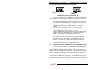
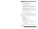
The two
F/H switches are located next to each Fast Ethernet port on Magnum
528’s. When the two Fast Ethernet ports of a Model 528 are set to operate at fixed
100Mb speed (no auto-negotiation), manual selection of half or full duplex at 100Mb
567
FDX
UPLINK
U
p
-link Switch
PWR
RX
LK
AUTO
F/H
FH FH
L K RX
F/H
100
10
TX RX
100 Mb
ST Connector (Magnum 528F only)
AUTO
PWR
F/H F/H
10
LK/RX
FDX
100100
10
1
2
F/H Switch (Magnum 528 only)


