


GBC 1264WF/1244WF Operation Manual
© 2006 General Binding Corporation Page 26
Section 10: Applications
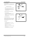
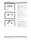
The 1244 WF & 1264 WF can accommodate Poly-in or Poly-out films. Poly-out means the
adhesive is on the outside of the roll. Each film requires a slightly different loading procedure.
Refer to the Webbing diagrams at the end of this section.
The shiny side of clear film must contact the heating components with the dull sides (adhesive
side) facing out. Use caution when loading Matte or Delustered film since both sides appear
dull.
The top and bottom rolls of laminating film must be of the same width and be present
simultaneously.
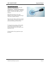
Film Loading & Threading
The top and bottom rolls of laminating film must be of the
same width and be present simultaneously. A Small amount
of adhesive will “squeeze out” during Lamination.
Hardened adhesive deposits can damage the heat rollers.
CAUTION:
Adhesive will deposit on the rollers if:
Only one roll is used.
Different widths of rolls are loaded together.
Either roll is loaded adhesive side against a heat roller.
One or both rolls of film are allowed to run completely
off its core.
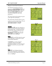
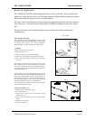
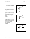
The adhesive side of the film is on the inner side of the web
(Fig. 1A & B). The shiny side of clear film must contact the
heat rollers. The dull side of the film contains the adhesive.
Use extreme caution when loading delustered (matte) film
as both sides appear dull.
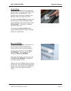
Always change the top and bottom supply rolls at the same
time. Near the end of each roll of GBC laminating film is a
label stating “Warning-End of Roll”. The appearance of
this label on either the top or bottom roll requires that new
rolls of film be installed as soon as the item presently being
laminated completely exits the rear of the laminator.
Do not introduce any additional items into the laminator
when the warning label is visible.
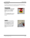
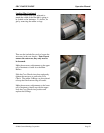
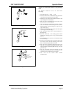
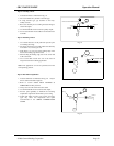
To load a roll of film: (Fig.2)
1. Pull the swing out shaft clevis pin up.
2. Swing shaft outward.
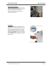
3. Slide the roll of film onto the film shaft ensuring
Adhesive side is out.
4. Push the film shaft back into the film shaft Support
saddle.
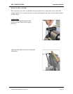
5. Push the clevis pin down.
6. Center the roll of film.
Fig. 1A & B
Fig. 2
1
5
2
3
4
6
=