


6
Features Guide
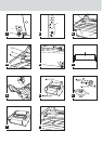
A. POWER SWITCH:
Located at the back of the machine,applies power to the laminator.
The ‘ON’ position is indicated by the ‘ ’ symbol.The ‘OFF’ position
marked ‘ ’ symbol (figure 1).
B. CONTROL PANEL: (figure 2)
• POWER LAMP ( ): Indicates that the laminator is plugged in and
the main power switch is in the ‘ON’ ( ) position.
• READY LAMP ( ):This will illuminate when the laminator has
reached operating temperature.
• STANDBY SWITCH ( ): Push to turn laminator on or off when
main power switch at the rear of machine is in the ‘ON’ ( )
position.
• RUN / STOP / REVERSE SWITCH ( ):Controls the
operation of the rollers.Select ‘RUN’ ( ) position to laminate.
Select ‘STOP’ ( ) position when the laminated item has passed
through the laminator. Select the ‘REVERSE’ ( ) position to
clear mis-feed,jams or wrap-ups.
• TEMPERATURE CONTROL KNOB ( ):Use to select appropriate
laminating temperature.Refer to the laminating guide on the feed
table to find the recommended setting.
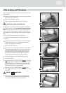
C. HEAT SHIELD: (figure 3a)
Prevents inadvertent contact with the heat shoes.
D. FEED TABLE: (figure 3a)
The Feed Table is used to position items for lamination. The
laminator will operate only when the Feed Table and Feed
Table Latch are properly installed.
E. FEED TABLE LATCH: (figure 3a)
Used to lock the Feed Table into position and activate an interlock
switch.The latch is located on the right underside of the Feed
Table.The Feed Table can be removed by retracting the latch and
lifting the table upward and away from the laminator.
F. FEED TABLE GUIDE:(figure 3a)
The Feed Table Guide aligns items to be laminated and is used to
insure that longer items are fed into the laminator straight.The
Feed Guide may also be used to feed smaller items side by side.
Position the feed guide toward the centre of the Feed Table and
place the items to be laminated against each side of the Feed
Guide as they are being introduced into the laminator.To position
the adjustable guide,lift the guide and slide it to the desired
position.
G. HEAT SHOES: (figure 3b)
Teflon coated heat shoes melt the adhesive on the laminating film
before the nip rollers compress it.
H. IDLER BARS: (figure 3b)
The Idler Bars,located near each supply roll, are used to direct the
film to the heat shoes.The lower Idler Bar is attached to the Feed
Table to facilitate easy film loading.
I. NIP ROLLERS: (figure 3b)
The Nip Rollers are located behind the heat shoes.The nip point is
where the heated film is compressed and pulled through the
laminator.
J. PULL ROLLERS: (figure 4)
The Pull Rollers are located at the back of the laminator.They
simultaneously pull the film through the laminator and provide
tension as the film cools to provide good quality lamination.
K. REAR SLITTER: (figure 4)
Used to cut the film where it exits the rear of the laminator.
L. FUSE: (figure 4)
The Fuse is an electrical safety device,located under the main
power switch.
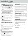
M.SUPPLY ROLL:(figure 5)
The Film Supply Rolls have core plugs inserted into each end of the
rolls.The left and right plugs are of a different color and diameter.
The color and diameter of end plugs correspond to the size of the
holder and color sticker located on the side plate of the laminator
(figure 5,a & b).
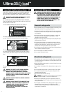
N. AUTO SHUT-OFF:
After one hour of inactivity the laminator will shut down.To activate
the laminator, with the main power switch in the ‘ON’ ( ) position,
push the Standby Button ( ) on the control panel and wait for the
ready light ( ) to illuminate.