


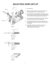

5
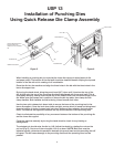
USP 13
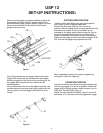
SET-UP INSTRUCTIONS:
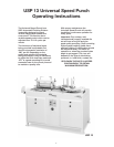
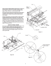
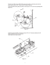
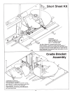
After the punching die is properly installed, position the
back gauge rail (#108, Figure 7) slightly ahead of the
punch die back gauge so that a piece of paper can slide
freely into the throat of the die and not hit the back
gauge of the punch die.
Cam (#37) activates the rear jogger (#34) and the side
jogger (#29). Adjust the cam so that when the longest
punch pin appears in the throat of the punching die, the
rear jogger (#34) should have just reached the full
vertical position.
Cam (#44) activates the front stop (#26). Adjust the cam
so that when the front stop finger (#100) reaches the full
vertical position, the side jogger (#29) starts its cycle
inward.
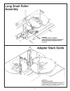
Loosen locking bolt (S40) under front bearing block
(#93, Figure 9) prior to setting registration.
Position the front stop (#26) so it is in its full up
position. Place a sample sheet of paper against the front
stop and punch paper. If the punch pattern is not
centered on the paper, adjust the front stop by turning
the front stop adjustment rod (#117) until the punch
pattern is centered. Once the front stop is set properly,
adjust the rear jogger so that it touches the paper. To do
this, turn the rear jogger stop adjustment (#118).
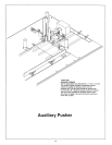
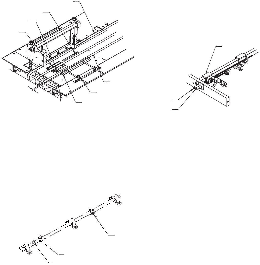
SETTING REGISTRATION
CONVEYOR SYSTEM
Cycle this machine manually by turning the hand wheel
until the rear jogger is in its full up position. Install side
jogger (#29) to slightly buckle a sheet of paper. Lock in
place with T-knobs (#248, Figure 7).
Adjust the outer transfer belt (#255, Figure 7) so that it
sets about 1/4” (.25) away from fully jogged side jogger.
When registration is set, lock in place by tightening
locking bolt. (S40, Ref. Page 30).
Figure 7 Figure 9
Figure 8
248
29
.25
26
34
100
108
OUTER BELT
117
118
93
44
37
43