


111
170
83
127
1.0
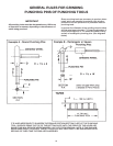
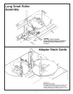
Figure 10
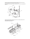
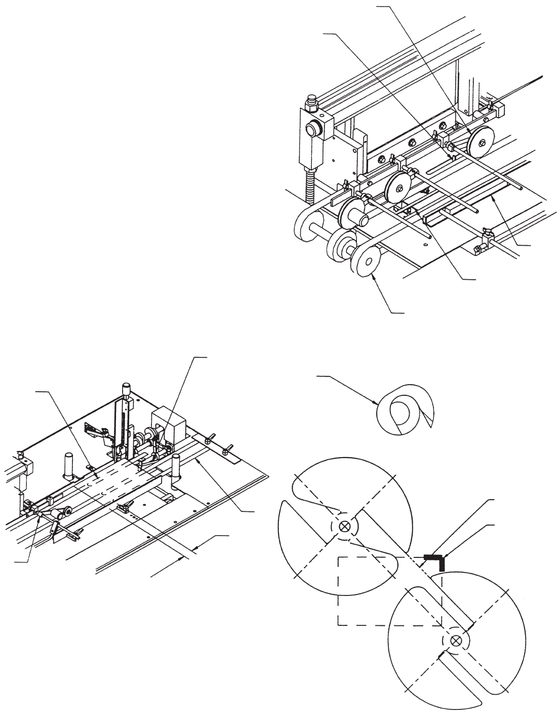
Figure 12
CLAW
THESE SURFACES
TO BE IN LINE
46
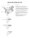
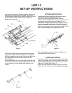
Place a sheet of paper against pusher (#111) in its home
position (rear). Install the three paper support straps
(#127 & #83, Figure 10) 1” away from the edge of the
paper. Straps must be on top of transfer belts.
Cycle the machine by hand until the pusher has pushed
the paper to its furthest point. Install long small roller
assembly (#170, Figure 10) so that the small pulley is
top of paper.
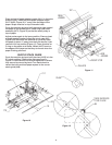
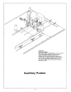
Adjust pusher again to its home position. Place a sheet
of paper against pusher. Adjust the punch cam (#43,
Figure 8) so that when the machine is cycled by hand,
the paper is about 1” away from the front stop as it just
reaches it full up position (Figure 11). There must be an
O-ring on the paper at all times. Wheel (#167) is set on
the edges of the paper so that they turn even when the
paper is being punched.
SUPPLY STACK GUIDE
Cycle the machine by hand until the claw (#103) is in the
5 o’clock position. Position the disks as shown in
Figure 12. Disks should not be over-tightened to where
they cannot be moved by hand. Turn hand wheel to
retract the knife and load paper square to the corner
stack guide (#46).
Figure 11
167
REAR
JOGGER
SIDE
JOGGER
FRONT STOP
PULLEYS
6