


Chapter 2: Installation
GE-DS-82 and 82-PoE Ethernet Managed Switch User Manual 17
NOTE: Connection to the Managed Switch requires UTP Category 5 network cabling
with RJ-45 tips. Refer to the Cabling Specification in Appendix A for further
information.
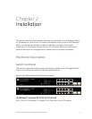
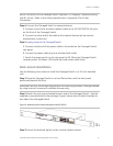
Step 4: Connect the Managed Switch to network devices.
A. Connect one end of a standard network cable to the 10/100/1000 RJ-45 ports
on the front of the Managed Switch.
B. Connect the other end of the cable to the network devices (printer servers,
workstations, routers etc).
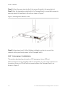
Step 5: Supply power to the Managed Switch.
A. Connect socket end of the power cable to the socket on the Managed Switch
rear panel.
B. Connect the power cable plug to a standard wall outlet.
C. Switch the power switch on the rear panel to ON. When the Managed Switch
receives power, the Power LED should light and remain solid Green.
Rack-mount Installation
Use the following instructions to install the Managed Switch in a 19-inch standard
rack.
Step 1: Place the Managed Switch on a hard flat surface, with the front panel
positioned towards the front.
CAUTION: Use only the screws supplied with the mounting brackets. Damage caused
by using incorrect screws will invalidate the warranty.
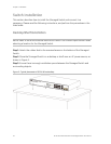
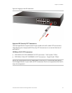
Step 2: Attach the rack-mount bracket to each side of the Managed Switch. Use the
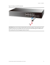
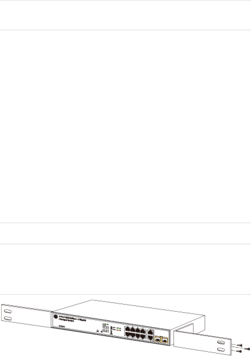
supplied screws attached to the package. Figure 6 shows how to attach brackets to
one side of the Managed Switch.
Figure 6: Attaching rack-mount brackets to the GE-DS-82
Step 3: Secure the brackets tightly, but do not over tighten screws.