


GEI-100305 Auxiliary Drive to ISBus Interface Board IS200ADII
•
••
•
11
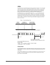
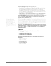
LED Indicators
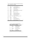
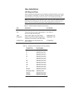
The LEDs on the ADII board are only intended for diagnostic purposes. See Table 7
for a description of the LED indications. The drive’s display will show any ISBus
faults or ADII board interface faults.
Note Debug LEDs DBG1A (DS3) and DBG1B (DS4) are for manufacturing test
only.
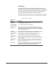
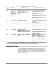
Table 7. ADII Board LED Indicator Descriptions
LED Mnemonic Description
DS1 Bus Active On if LAN pulses are detected and in an active state. If this LED
is not on, then the ISBus Controller has not detected any LAN
pulses and is not in an active state.
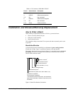
DS2 Bus Online On or flashing if modulation on the LAN is detected. If this LED is
not on, then the ISBus Controller is not online. See Table 8 for a
description of flashing indications.
DS3 Debug1A Manufacturing use only
DS4 Debug1B Manufacturing use only
DS5 Bypass Relays
Enabled
On if these relays are being driven (meaning the drive’s P5 is
OK). If this LED is not on, then P5 (+5 V) is below 4.6 V or P24
(+24 V) is too low to drive these relays.
DS6 Xmit Data On if there is data being transmitted. If this relay is not lit (dimly),
then there is no transmitted data.
(because this LED is directly across the differential transmit lines,
it is being pulsed and will appear to be very dim)
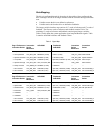
Table 8. DS2 LED Indicator Flashing Indications
Modulatio
n Present
ISBus
Controller
Core State
DS2
Flashes/Second
No x Off Solid
Yes RESET 1
Yes OFF LINE 2
Yes STANDBY 3
Yes ONLINE On Solid