


•
••
•
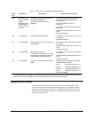
Auxiliary Drive to ISBus Interface Board IS200ADII GEI-100305
18
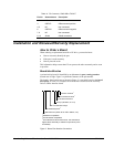
Care must be taken to keep the ISBus cables away from any
high voltage wires and any electrically noisy wires. Keep the
cables tight to the ADII board carrier and use the tie down strap
holders to hold the cables close to the ADII board and away
from the power supply board.
10. Install cable ties to the ISBus cables on the ADII board strain reliefs and on the
other cables/locations as necessary to keep the cables tight to the board and
board carrier, and away from the power supply board.
11. Raise the board carrier back up into its normal position, slide the board carrier
retainers in to secure it in this position, and close the drive cabinet door.
Replacement Procedures
To prevent electric shock, turn off power to the board,
then test to verify that no power exists in the board
before touching it or any connected circuits.
To prevent equipment damage, do not remove, insert, or
adjust board connections while power is applied to the
equipment.
Ø
ØØ
Ø To remove the ADII Board from the drive
1. Make sure that the drive in which the board is to be removed has been
deenergized. (Refer to the appropriate User's Guide for complete de-energizing
procedures and follow all local practices of lock out/tag out.)
2. Open the drive’s cabinet doors, and using equipment designed for high voltages,
test any electrical circuits before touching them to ensure that power is off.
3. Carefully remove the board from the drive as follows:
a. Release board carrier retainers by pulling them forward.
b. Lift up and rotate the front board carrier out and down until it is resting on
its stops.
c. Disconnect all cables and wires from the ADII board (2PL, TX and RX
ISBus, CHASSIS ground wire, LNPL, and COM1 wire). (The COM1 wire
runs parallel to the LNPL cable.)
d. Pull back on the four locking tabs and lift board up and off of the board
carrier.