


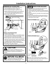
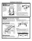
Installation Instructions
6
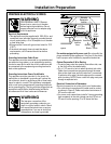
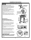
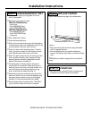
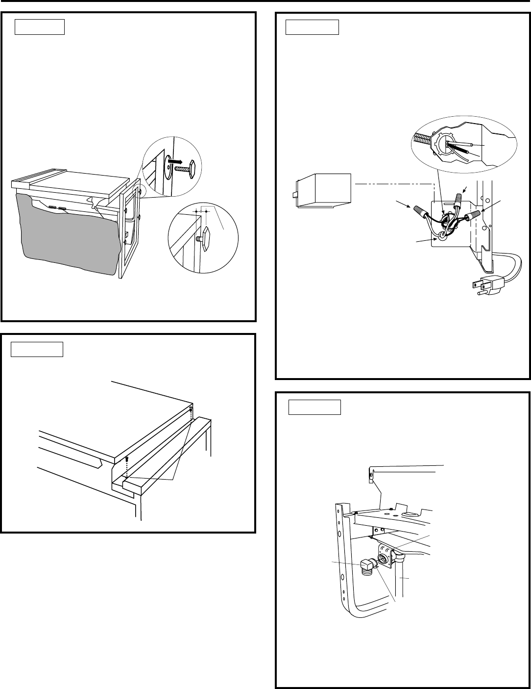
• Do not over tighten 90° elbow, water valve bracket
could bend or water valve fitting could break.
• Position the end of the elbow to face the rear of the
dishwasher.
STEP 5 INSTALL 90° ELBOW
• Wrap 90° elbow with thread seal tape.
• Install a 90° elbow onto the water valve.
Figure M
Figure K
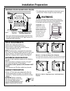
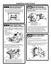
STEP 3 REMOVE TOEKICK
• Remove the two toekick screws.
• Screw leveling legs back into the dishwasher
frame, approximately 1/4" from frame as shown.
Figure J
STEP 2 REMOVE WOOD BASE,
INSTALL LEVELING LEGS
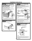
IMPORTANT – Do not kick off
wood base! Damage will occur.
• Move the dishwasher close to the installation
location and lay it on its back.
• Remove the four leveling legs on the underside of
the wood base with an adjustable
wrench or 15/16" socket.
• Discard base.
Approx.
3/4"
T
oekick
Remove 2
Toekick Screws
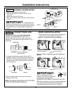
• Connect incoming power cord white (or ribbed) to
dishwasher white, black (or smooth) to black and
ground to dishwasher green wire. Use UL listed
wire nuts of appropriate size.
• Replace junction box cover. Be sure wires are not
pinched under the cover.
STEP 4 INSTALL POWER CORD
Skip this step if dishwasher will be direct wired or
has a factory installed power cord.
The power cord and connections must comply with
the National Electrical Code, Section 422 and/or local
codes and ordinances.
• Maximum power cord length is 6 feet.
Figure L
Front of Dishwasher
90°
Elbow
Thread
Seal Tape
Fill
Hose
Water Valve
Bracket
White
Ground
Black
Check That White, Black and
Green Dishwasher Wires Are Threaded
Thru Small Hole in Bracket
Remove
Junction Box
Cover
Insert Power
Cord Wires Thru
Strain Relief
and Tighten
Use UL Listed
Wire Nuts
A
C
B
D