


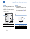

SuperBus 2000 Concord 4 GSM Module
Installation Instructions
2
Installation
Before you install the system, the module must be activated (see
Account creation on page 6). The account creation process auto-
matically activates the module within 24 hour.
Installation consists of finding a good mounting location for the
module to optimize wireless signal strength, mounting the
module, wiring the module, and installing a case tamper.
Installation guidelines
Use the following installation guidelines:
• The module draws a maximum of 65 mA (continuous) in
PowerSave mode and 100 mA (continuous) in Idle Mode
and Connected Mode from the panel. The module can draw
up to 1600 mA (instantaneous peaks) from the panel.
• Do not exceed the panel total output power when using
panel power for bus devices and hardwired sensors (refer to
your panel documentation).
• Use four-conductor, 22 or 18 gauge stranded wire to
connect the module to the panel. Table 3 shows the
maximum wire length for each gauge.
Tools and supplies needed
You will need the following tools and supplies:
• Small blade and Phillips screwdriver.
• Drill and bits for screws and/or anchors.
• Wire cutter/stripper.
• Four-conductor, 22-gauge or larger stranded wire.
• #6 panhead screws (4 included).
• Wall anchors (4 included).
• 2 Kohm EOL resistor (included).
Module location guidelines
Use the following guidelines to choose a location for the module:
• Check the signal strength before choosing a location. Do a
walking signal strength test by powering the module off the
battery directly (connect the GND and +12V terminals).
After two minutes, GSM status LED 4 will flash between
one and five times, equivalent to the number of bars on a
cell phone. We recommend a signal level of two or higher.
• Avoid mounting the module in areas with excessive metal or
electrical wiring, such as furnace or utility rooms.
• Locate the module near an outside wall, preferably on an
upper level.
• Leave 12 to 18 in. (30 to 45 cm) of open space above the
module for the antenna.
• For homes or businesses located in canyons or with hills
nearby, it is necessary to place the antenna higher in the
building.
Mounting
To mount the module, do the following:
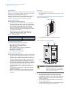
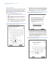
1. Press down on the top of the enclosure cover (Figure 3) and
set it aside.
Figure 3. Removing the cover
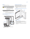
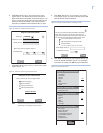
2. Screw the antenna onto the antenna jack (Figure 4).
Figure 4. Antenna jack and mounting holes
3. Place the module backplate on the wall at the desired
mounting location, check for level, and mark the three
mounting holes and the wire access area (Figure 4). Be sure
to leave at least 12 to 18 in. (30 to 45 cm) above the back-
plate for the antenna.
4. Set the backplate aside and drill holes at the mounting and
wire access area locations.
5. Use wall anchors where studs are not present and secure the
backplate to the wall with the enclosed screws.
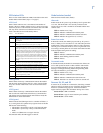
Table 3. Maximum wire length
Gauge Maximum wire length to panel
22 gauge 40 ft. (12.2 m)
18 gauge 90 ft. (27.4 m)
CAUTION: You must be free of static electricity
before handling electronic components.
Touch a grounded metal surface before
touching the circuit board.
Press down here
Mounting
hole
Mounting
hole
Wire access area
Mounting
hole
Antenna
jack