


5
GSM status LEDs
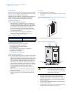
There are four small GSM status LEDs, located below the serial
number label on the module (Figure 1 on page 1).
LED 1 (red)
LED 1 flashes when an error is encountered. The number of
flashes is the error number. If there are two or more errors at the
same time, the errors will be flashes one after the other. The LED
will stay off for at least four seconds between errors.
Table 5 describes the errors indicated by LED 1.
LED 2 (yellow)
LED 2 flashes with every communication between the module
and the panel. Normal pattern calls for a series of quick flashes
every two seconds in Idle mode or four seconds in PowerSave
mode.
LED 3 (green)
LED 3 flashes with every communication between the module
and its radio unit in Idle mode and with every communication
with Alarm.com in Connected mode. In PowerSave mode, this
LED flashes in unison with LED 2.
LED 4 (green)
LED 4 indicates the GSM signal level as a number of flashes (1
to 5). The signal level is updated every eight seconds. No flashes
indicate one of the following:
• The module is in PowerSave mode or in Connected mode.
• The module is powered up or has just exited PowerSave
mode.
• There is no GSM tower coverage in the area.
In Connected mode, the LED toggles on and off.
Module states (modes)
There are three module states (modes).
Idle mode
In Idle mode, the AC power is up, the battery level is greater than
11.5 volts, and the module is not currently connected to the
Alarm.com servers. This is normal for the module and the most
common state.
LED 1. Flashes errors, if any.
LED 2. Indicates communication with the panel.
LED 3. Indicates communication with the radio unit.
LED 4. Indicates the signal level (1 to 5 bars).
PowerSave mode
In PowerSave mode, the module just powered up, AC power is
down, or battery level is less than 11.5 volts. The radio part of the
module draws 10 mA in PowerSave mode. It is fully functional
and will go into Connected mode as soon as a signal needs to be
sent. Doing a manual phone test will switch the module into Idle
mode and update the signal level reading.
LED 1. Inactive.
LED 2. Indicates communication with the panel.
LED 3. Same flashing pattern as LED 2.
LED 4. Inactive.
Connected mode
In Connected mode, the module is connected to the Alarm.com
servers and reported an alarm or other condition. The module
stays in Connected mode for at least six minutes after the last
message is exchanged. Entering Installer Programming mode
will cause the module to go into Idle mode.
LED 1. Flashes errors, if any.
LED 2. Indicates communication with the panel.
LED 3. Indicates communication with Alarm.com.
LED 4. Alternates two seconds on, then two seconds off.
Sensors 94, 95, and 96
If sensors 94, 95, and 96 are not learned in, after doing a manual
phone test, the text for these sensors will display important infor-
mation for troubleshooting purposes. Alarm.com technical
support staff may request this information during service calls.
Sensor 94 text. SIM card number.
Sensor 95 text. Type of central station reports enabled.
Sensor 96 text. Serial number.
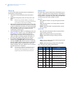
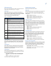
Table 5. Error descriptions
Flashes Error description
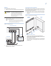
1 Module cannot communicate with the panel. Check wiring
between the panel and the module. Make sure the bus wires are
not swapped.
2 The SIM card is missing. The SIM card holder can be found in the
gateway just below the antenna (Figure1 on page 1).
3 This is a common error if the module takes more than ten seconds
to register with the GSM network. It is normal for this error to show
up for approximately 30 seconds while the module registers with
the GSM network (at power up, for example). If it persists, then the
module is unable to register with the GSM network. Check LED 4
for the signal level. If the signal is too low, change the module’s
location or use a higher gain antenna. If the signal is good, the
module may be roaming on a GSM network that doesn’t partner
with ATT-Cingular. If the module had been communicating in the
past, there may be new interference from some other device or
building.
4 The module is registered on the GSM network, but cannot connect
with Alarm.com. Contact Alarm.com Technical Support.
5 The radio portion of the module is not working correctly.
6 This is an error only if it persists for more than a minute. Otherwise,
it is an indication that the module is fixing an unusual condition
regarding the communication with the GSM network.
7 Access Code Lock is on. The module cannot do certain operations
with the panel. This option should be turned off at the panel
(System Programming - 0003).
8 Contact Alarm.com Technical Support.