


5
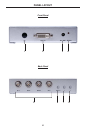
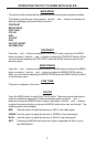
PANEL DESCRIPTIONS
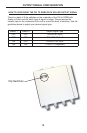
1 IR Receiver
This receiver will receive commands from an optional RMT-SR-IR remote
control. This receiver requires line-of-sight to the IR remote control for successful
operation.
2 DVI-I Input
This receptacle will accept digital and analog signals. When using a analog VGA
source use a VGA to DVI-A type cable. This receptacle will accept DVI-D, DVI-A
or DVI-I cable types.
3 5V DC Power Input
Connect the included 5V DC power supply between this receptacle and an open
wall power socket. Once the power supply is properly connected the power LED
indicator will become active.
4 Power LED Indicator
Tis LED indicator will become active once the included 5V DC power supply has
been properly connected and is supplying power to the unit.
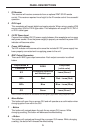
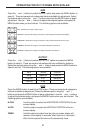
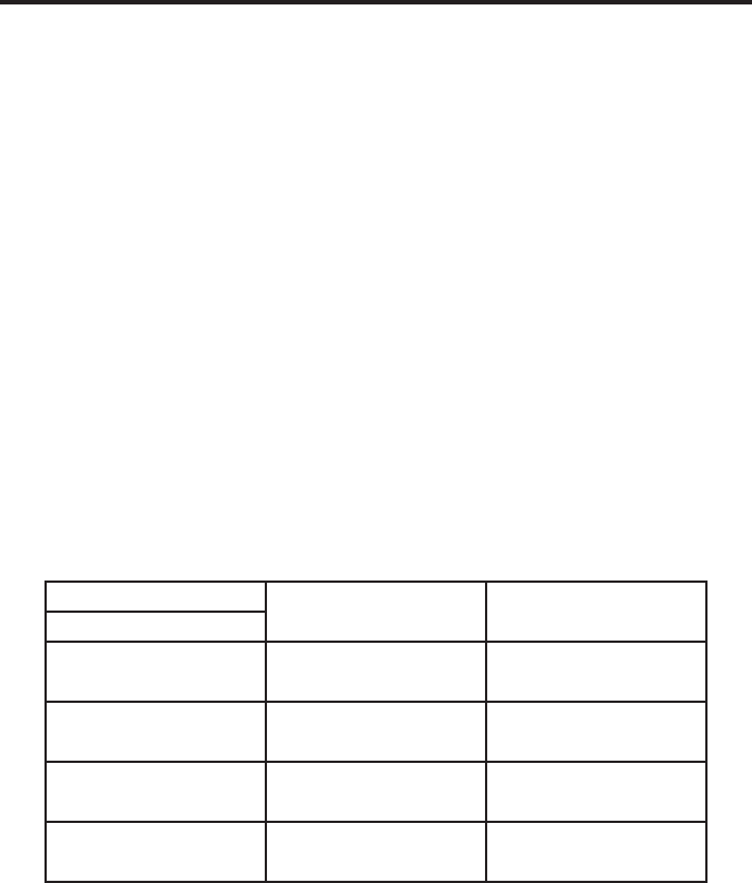
5 BNC Output Connectors
There are 4 BNC type output connectors. Each output connector is outlined
below:
Output Mode ►
RGBS
Component
(cable color)
Connector ▼
S/Y
Composite Horizontal
and Vertical sync
Luma (Green)*
R/Pr Red Red - Luma (Red)
B/Pb Blue Blue - Luma (Blue)
G/Y Green Luma (Green)*
*Either of these connectors can be used for the luma (green) signal when using component video.
6 Menu Button
This button will open the on-screen GUI and will operate as a confi rmation when
changing option from within the GUI.
7 - Button
This button will navigate down through the on-screen GUI menus. While
changing a setting, this button will decrease the effect/setting.
8 + Button
This button will navigate up through the on-screen GUI menus. While changing
a setting, this button will increase the effect/setting.