


8
RPM SIGNAL FAILURE (FLASHING RED
OVERSPEED INDICATOR)
If the R-200A controller does not receive a signal
from the engine flywheel sensor, the R-200A control-
ler cannot maintain the generator output frequency
or monitor for an overspeed condition. If this sig-
nal is lost the R-200A controller will shut down the
engine as follows:
RPM SIGNAL FAILURE DURING CRANKING
The engine control board (R-200A controller) will
monitor the engine speed signal during engine crank-
ing. If the control board does not see a valid signal
within the first four seconds of each crank cycle it
will stop the crank cycle, lock out on a shut down
fault and flash the overspeed LED.
RPM SIGNAL FAILURE DURING RUNNING
Running mode is handled differently because there
is always the possibility the engine could slow down
or stop running due to a temporary overload. To
avoid shutting down and latching out on a temporary
problem the following is done. If the engine is up and
running, and the control board stops receiving a valid
engine speed input signal it will respond as follows:
1. It will close the throttle.
2. It will shut down the engine by turning off the fuel
supply.
3. It will wait for 15 seconds to ensure the engine
has stopped.
4. It will then energize the starter and monitor the
engine speed signal.
A. If the control board does not see the engine
speed signal it will stop the crank cycle, lock out
on fault, and flash the overspeed LED.
B. If the control board does see the engine speed
input signal during cranking it will start and run
the engine normally. If the engine speed signal is
again lost while running it will repeat the above
procedure one more time.
C. If the failure should repeat a third time, the con-
trol board will shut down the engine, lock out on
fault, and flash the over speed LED.
OVERCRANK (RED LED INDICATOR)
Occurs if the engine has not started within the total
90 second crank cycle. This is a latched fault and will
shut down the engine.
INVALID DIP SWITCH SETTING
(ALL RED LED’S ON)
All five (5) RED LED’s on the front panel will be ON
all the time if DIP switch position 5 is not set cor-
rectly.
ALARM CANCEL
When the generator is shut down on a latched fault or
latching alarm, the AUTO/OFF/MANUAL switch must
be set to the OFF position to turn off the correspond-
ing fault LED. Prior to moving the switch to the OFF
position, record which LEDs are ON or FLASHING
and the date on the back cover of this manual.
AUTOMATIC TRANSFER SWITCH (ATS
MODE)
When this generator, along with an RTS-type or HS-
type automatic transfer switch has been installed and
connected, a circuit board in the generator control
panel constantly monitors the utility voltage and con-
trols the operation of the transfer switch.
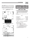
To implement this mode of operation, Position 2 of
the eight-position DIP switch, which is located on the
generator circuit board (see Figures 1 and 2), must
be in the OFF position. In ATS Mode utility voltage
sensing, weekly exercising, and load transferring is
under the control of the generator.
Should the utility voltage drop below a preset value,
and remain at this low voltage for a preset amount
of time, the generator cranks and starts. After the
generator starts, the transfer switch transfers the
load circuits to the generator so the generator can
power them. When the utility source voltage has been
restored, the transfer switch re-transfers the load
circuits back to the utility source voltage and the gen-
erator shuts down.
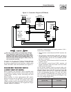
The transfer switch is controlled by the generator
circuit board via control wires 23 and 194. Wire 23
connects the collector of an NPN transistor on the
generator circuit board to the “low side” (Terminal
23) of the transfer relay coil in the transfer switch.
Wire 194 connects positive battery voltage from the
generator circuit board to the “high side” (Terminal
194) of the transfer relay coil in the transfer switch.
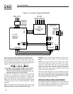
In order for the generator utility voltage sensing
function to work, it is necessary to provide a 5 amp
fused 240VAC for 240V or 480V systems or 208VAC
utility source connection (depending on the generator
being used) from the transfer switch main N1 and N2
terminals to the generator wiring panel N1 and N2
terminals (See Figure 4).
General Information
R-panel Technical Manual