


10
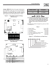
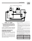
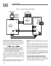
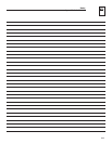
Route the 2-wire start control wires through suit-
able, approved conduit which is separate from the
AC power leads. Connection of wire 178 to wire 183
by relay contact closure action (volt free switch con-
tacts) in the transfer switch must result in generator
engine cranking and startup (see Figure 5).
Do NOT connect battery voltage, utility voltage
(N1/N2) or load voltage (T1/T2) to either the
178 or the 183 2-wire start terminals as this will
damage the generator control board.
In order for the generator battery charger function
to work, it is necessary to provide a 120Vac util-
ity source connection to the generator wiring panel
LINE, NEUTRAL and GND terminals (see Figure 5).
When in GTS mode, the control board will respond
as follows based on the AUTO/OFF/MANUAL switch
position.
OFF: The generator will not start and run in this
position. Only the System Ready LED and the Low
Battery LED are active in the GTS OFF mode.
MANUAL: The control board will start and run the
generator whenever the switch is in the manual posi-
tion.
AUTO: The control board will monitor the 2-wire
start circuit. When the 2-wire start wire 178 is con-
nected to 2-wire start wire 183, via a relay contact
closure in the W-type transfer switch, the control
board will start and run the generator. When the
2-wire start wire connection is opened the control
board will stop the generator.
When the control board is in AUTO, MANUAL or OFF
(GTS mode) the GREEN System Ready LED will flash
(five (5) seconds ON, one (1) second OFF) to indi-
cate that the transfer switch is performing the utility
monitoring and transfer functions.
VOLTAGE REGULATOR ADJUSTMENT
Although adjustment potentiometers are provided on
the voltage regulator installed in the control panel,
the voltage regulator potentiometers have been set at
the factory and should NOT be re-adjusted.
General Information
R-panel Technical Manual
FROM UTILITY
TO LOAD
FEEDER CIRCUITS
LOAD
DISTRIBUTION
PANEL
GENERATOR
194
23
178
183
N2 N1
178
183
W-TYPE
TRANSFER
SWITCH
MAIN LINE
CIRCUIT
BREAKER
OR FUSE
LINE
NEU
GND
CHARGER
120 VAC
E1 E2 (E3)
N1 N2 (N3)
T1
T2
(T3)
E1 E2 (E3)
Figure 5 - Connection Diagram (GTS Mode)