


Table of Contents
R-panel Technical Manual
1
Safety Rules ........................................ Inside Front Cover
General Information ......................................................... 2
Introduction ........................................................... 2
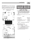
Control Board Dip Switch & Jumper Settings .......2
Generator Operation ..............................................5
Engine Timing ........................................................5
Utility Failure .........................................................5
Manual Mode ......................................................5
Auto Mode ...........................................................5
Exercise Mode ..................................................... 5
Utility Restored ......................................................5
Initial Cranking ......................................................5
Active Alarm ...........................................................6
Re-crank ................................................................6
Normal Exercise Mode ...........................................6
Low Speed Exercise ...............................................6
Auto Start .............................................................. 6
Manual Start ..........................................................7
System Ready (Green LED Indicator) ....................7
Low Fuel Pressure (Yellow LED Indicator) ............. 7
Low Battery (Red LED Indicator) ...........................7
Low Oil Pressure (Red LED Indicator) ...................7
High Coolant Temp (Red LED Indicator) ................ 7
Low Coolant Level (Flashing Red
High Coolant Temp LED Indicator) .....................7
Overspeed (Red LED Indicator) ............................. 7
RPM Signal Failure
(Flashing Red Overspeed Indicator) ....................8
RPM Signal Failure During Cranking .................. 8
RPM Signal Failure During Running ....................8
Overcrank (Red LED Indicator) ............................. 8
Invalid Dip Switch Setting (All Red LED's On) .......8
Alarm Cancel .........................................................8
Automatic Transfer Switch (ATS Mode) .................8
Engineered Transfer Switch
(2-wire Start GTS Mode) .....................................9
Voltage Regulator Adjustment ..............................10
R-200A J1 Connector (23 Pin,
Gray=1800 rpm, White=3600 rpm) ..............11
R-200A J2 Connector (14 Pin White) ................11
2A and 10A Battery Chargers ...............................11
2A, 12VDC Battery Charger ..............................12
10A, 12VDC Battery Charger ............................12
Notes ...................................................................................13
AUTHORIZED SERVICE
DEALER LOCATION
To locate the nearest AUTHORIZED
SERVICE DEALER, please call this number:
1-800-333-1322
DEALER LOCATION INFORMATION
CAN BE OBTAINED AT THIS NUMBER,
or visit the website at www.generac.com.
Table of Contents