


12
DANGER
Storage batteries give off explosive hydrogen
gas. This gas can form an explosive mixture
around the battery for several hours after charg-
ing. The slightest spark can ignite the gas and
cause an explosion. Such an explosion can shat-
ter the battery and cause blindness or other
injury. Any area that houses a storage battery
must be properly ventilated. Do not allow smok-
ing, open flame, sparks or any spark producing
tools or equipment near the battery.
Battery electrolyte fluid is an extremely corro-
sive sulfuric acid solution that can cause severe
burns. Do not permit fluid to contact eyes, skin,
clothing, painted surfaces, etc. Wear protective
goggles, protective clothing and gloves when
handling a battery. If fluid is spilled, flush the
affected area immediately with clear water.
Do not use any jumper cables or booster battery
to crank and start the generator engine. If the
battery has completely discharged, remove it
from the generator for recharging.
Be sure the AUTO/OFF/MANUAL switch is set to
the OFF position, before connecting the battery
cables. If the switch is set to AUTO or MANUAL,
the generator can crank and start as soon as the
battery cables are connected.
Be sure the utility power supply to the battery
charger is turned off, or sparking may occur at
the battery posts as the cables are attached and
cause an explosion.
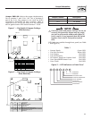
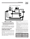
2A, 12VDC BATTERY CHARGER
Nominal Input AC Line Voltage .......................... 120Vac
Operating AC Line Voltage Range ................... 108Vac to
132Vac
Input AC Line Frequency ..............................50 or 60Hz
AC Line Fuse ......................... 2 Amp Slo-Blo, 5x20mm,
Littelfuse P/N 218002
Battery Fuse ........................................5 Amp, Littelfuse
Mini-Blade Fuse P/N 297005
Nominal Charge Rate ........................................ 2 Amps
Float Voltage (type) .........................................13.4 Volts
Battery Undervoltage Shutdown (typ) .............. 11 Volts
LED Indicators
AC Line Voltage > 108Vac ................Green LED ON
Battery Connected & Charging .........Yellow LED ON
(the Green LED must be ON to obtain a valid bat-
tery charging indication,
Yellow LED ON if charge current > approx 0.5
Amps)
Battery Current Drain (AC Power OFF) ........ 30mA (typ)
AC Line Connection........................... via terminal block
(AC Hot, AC Neut & GND)
Battery Connections .......................... via terminal block
(Pos +, Neg -)
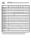
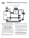
10A, 12VDC BATTERY CHARGER
Nominal Input AC Line Voltage ........................ 120Vac
Operating AC Line Voltage Range ......108Vac to 132Vac
Input AC Line Frequency .............................50 or 60Hz
AC Line Fuse ...................................... 5 Amp, 5x20mm,
Littelfuse P/N 218005
Battery Fuse ..............................15 Amp, Littelfuse ATO
Blade P/N 257015
Nominal Charge Rate ..................................... 10 Amps
Equalize Voltage (typ) ....................................13.8 Volts
Float Voltage (typ) .........................................13.0 Volts
Current at Equalize to Float Transition (typ) .. 5 Amps
Battery Undervoltage Shutdown (typ) ...............11 Volts
LED Indicators
AC Line Voltage > 108Vac ...............Green LED ON
Battery Connected & Charging ........Yellow LED ON
the Green LED must be ON to obtain a valid
battery charging indication,
Yellow LED ON if charge current > approx 2
Amps)
Battery Current Drain (AC Power OFF) .......30mA (typ)
AC Line Connections ......................... via terminal block
(AC Hot, AC Neut & GND)
Battery Connections .......................... via terminal block
(Pos +, Neg -)
Control Connections ......................AC Power Fail Relay,
Form C, 2Amps, 12Vdc
(N.O. Contact closes when ac line voltage is applied)
(N.O. Contact opens when ac line voltage is removed)
General Information
R-panel Technical Manual