


6
For the second system, connect MULTI OUT 2 from the Beacon II Smart
Controller to the MULTI IN on the Beacon II board on the Evaporator in this second
system. Then connect MULTI IN 2 from the Beacon II Smart Controller to the
MULTI OUT on the Beacon II board on the Evaporator on this second system. See
typical wiring diagram at the back of these instructions.
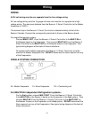
On systems with multiple evaporators the Beacon II Smart Controller must be wired to
the Master Evaporator first. DO NOT disconnect the Room sensor from any of the
Evaporators.
DO NOT CONNECT 24V & C BETWEEN EVAPORATORS.
The Beacon II Smart Controller and the evaporators are then connected in a daisy–
chain fashion. (See the wiring diagrams in the back of this manual)
A minimum 18 gauge wire should be used. All low voltage wiring must be run separate
from high voltage wiring.
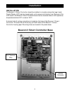
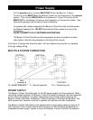
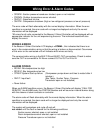
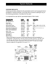
MULTIPLE SYSTEM CONNECTION
SYSTEM 1 SYSTEM 2 SYSTEM 3
SYSTEM 4
M = Master Evaporator S = Slave Evaporator CU = Condensing unit
POWER SUPPLY
The Beacon II Smart Controller gets it’s 24 VAC power supply from the evaporator. When
controlling multiple systems, the Beacon II Smart Controller is powered from the evaporator
of only one of the systems. If a power interruption occurs to the system supplying the
Beacon II Smart Controller, the Beacon II Smart Controller LCD screen will go blank. The
other systems will, however, continue to operate and maintain their box temperature.
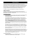
The Beacon II Smart Controller can be supplied with it’s own power supply by using a 24
VAC Universal Plug-in Power Source with a minimum of 300 mA. When powered by an
independent power supply, if power is lost to the Beacon II Smart Controller the systems
Power Supply