


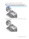
4.
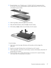
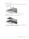
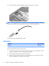
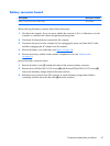
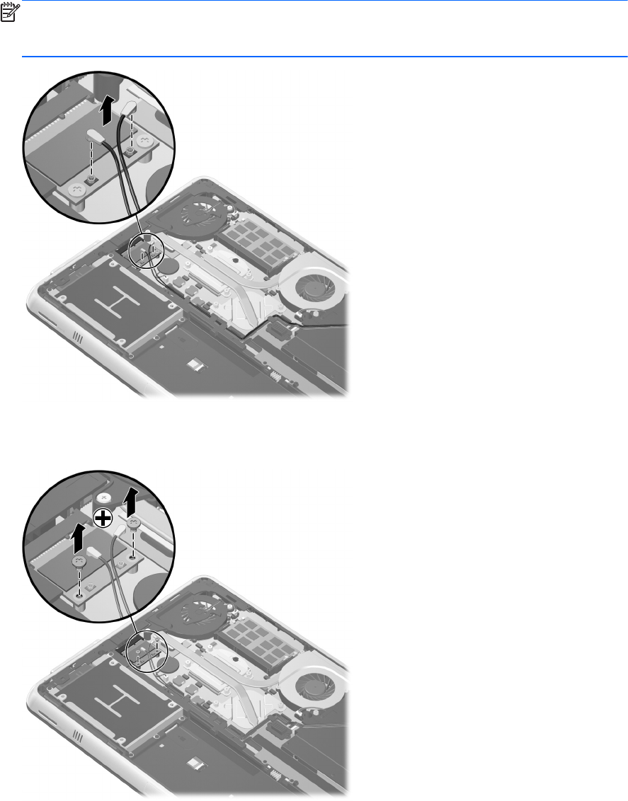
Disconnect the WLAN antenna cables from the terminals on the WLAN module.
NOTE: The 1/black WLAN antenna cable is connected to the WLAN module 1/Main/Tr1
terminal. The 2/gray WLAN antenna cable is connected to the WLAN module 2/Aux/Tr2
terminal. If a 3/yellow antenna cable is present, it is connected to the 3/Tr3 terminal.
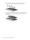
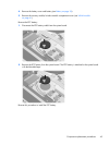
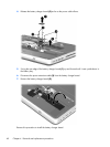
5. Remove the two Phillips PM2.0×2.83 screws that secure the WLAN module to the system board.
(The WLAN module tilts up.)
Component replacement procedures
43