


6Ć71 Removal and ReplacementC3187Ć90000
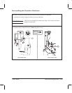
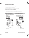
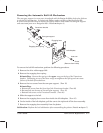
Removing the Automatic BailĆLift Mechanism
The camĆgear support is a new part, introduced with the DesignJet 220 to help solve failures
in the bailĆlift mechanism. It replaces the TeflonĆwasher solution of the DesignJet 200.
A service note describes how to remove the Teflon washers and install the camĆgear support
and associated parts on a DesignJet 200. (Details D chapter 9.)
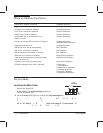
Engaging lever
EngagingĆlever spring
Screw
(Remove from inside)
Left sideplate
YĆtensioner bracket
CamĆgear support
Auto cam
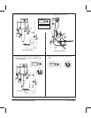
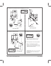
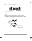
To remove the bailĆlift mechanism, perform the following procedure:
1 Remove the drive roller D page 6Ć69.
2 Remove the engagingĆlever spring.
Reinstalling: Connect the spring to the upper rung on the leg of the YĆtensioner
bracket. Connecting to one of the lower rungs overtightens the spring and can cause
failure of the bailĆlift mechanism.
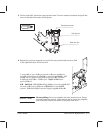
3 Remove the two screws from the camĆgear support. (Torx 15)
Reinstalling:
a. Remove the screw from the front leg of the YĆtensioner bracket. (Torx 20)
b. Reinstall the two screws on the camĆgear support. (Torx 15)
c. Reinstall the screw on the YĆtensioner bracket. (Torx 20)
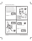
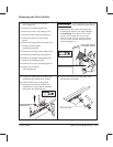
4 Slide the support to the left.
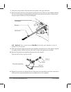
5 Remove the engagingĆlever screw from inside the left sideplate. (Torx 15)
6 On the inside of the left sideplate, pull the cam to the right and off the lever assembly.
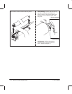
7 Remove the engagingĆlever assembly from the plotter.
Calibration: Perform the bail calibration after reassembling the plotter. (Details D chapter 7.)