


11
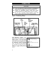
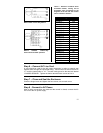
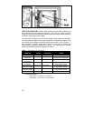
Figure 8 - Connection diagram for
Bodine 230V inverter-duty motors.
Figure 9 - Connection diagram for
Bodine 230/460V inverter-duty
motors wired for 230V operation.
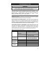
Table 3 - Direction of Bodine motor
driveshaft rotation, viewing end of
driveshaft, when connected per the
diagrams at the left and with control
set for “forward” direction
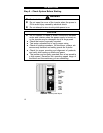
Bodine Motor Type Direction
30R2BEPP CCW
30R4BEPP CCW
30R2BEPP-D3 CW
30R4BEPP-D3 CW
30R2BEPP-D4 CCW
30R4BEPP-3N CCW
34R6BEPP-Z2 CCW
34R6BEPP-Z3 CCW
34R6BEPP-Z4 CW
34R4BFPP-E1 CCW
34R4BFPP-E2 CW
34R4BFPP-E3 CCW
34R4BFPP-E4 CW
34R6BFPP CW
34R6BFYP CW
42R6BFPP CCW
42R6BFPP-GB CW
42R6BFPP-F1 CW
42R6BFPP-F2 CCW
42R6BFPP-F3 CW
42R6BFPP-5N CCW
42R6BFPP-5H CCW
48R5BFYP CCW
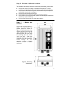
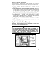
Step 6 – Connect AC Line Cord
A cord should be used for the AC power connection in order to properly seal
against water through the liquid tight fitting. Connect the hot side of the line to
“L1” and the neutral side to “L2.” Connect earth ground to the terminal labeled
“CHASSIS GROUND.” Tighten the barrier terminal block screws to 6 lb-in.
Step 7 – Close and Seal the Enclosure
Close the hinged cover and tighten the four screws, one at each corner.
Step 8 - Connect to AC Power
After all other connections are made and the control is closed, connect the AC
line cord to the AC power supply.