


18
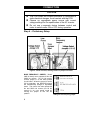
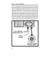
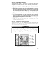
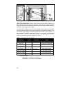
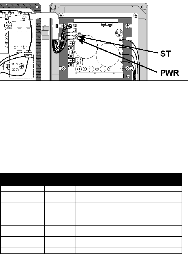
Figure 13 – Location of LED Status Indicators inside the enclosure
LED STATUS INDICATORS – Models 2995 contains two LED status indicators on
the printed circuit board inside the enclosure. One LED is a green Power On
indicator (PWR) that indicates the presence of the bus voltage and the operation
of the main control logic power supply.
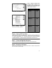
The other LED is a tricolor lamp (ST) that indicates a fault or abnormal condition.
The information provided can be used to diagnose an installation problem, such
as incorrect input voltage, overload condition and control circuit miswiring. It
also provides a “normal” signal that informs the user that all control and
microprocessor operating parameters are proper. The meaning of the different
colors and flash frequencies are explained in Table 5.
TABLE 5 – Interpretation of ST indicator LED
OPERATING
CONDITION
LED
COLOR
LED FLASH
FREQUENCY
CORRECTIVE
ACTION
Motor Running Normally GREEN SLOW FLASH* N/A
Motor Running, but in
Current Limit
RED STEADY, NO FLASH LED will return to slow flashing green
if overload is removed before trip
Motor Stopped due to
Current Limit Trip
RED QUICK FLASH*
Motor Stopped due to
Short Circuit
RED SLOW FLASH* Motor will restart automatically if
supply voltage is corrected
Motor Stopped due to
Control Under Voltage
RED/YELLOW QUICK FLASH* Motor will restart automatically if
supply voltage is corrected
Motor Stopped due to
Control Over Voltage
RED/YELLOW SLOW FLASH* Motor will restart automatically if
supply voltage is corrected
Normal Stop Condition YELLOW STEADY, NO FLASH N/A
*FLASH DEFINITIONS:
• Slow Flash = 1 second on, 1 second off
•
Quick Flash = .25 second on, .25 second off