


4–30 Maintenance and Service Guide
Removal and replacement procedures
Ä
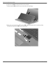
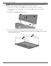
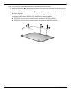
CAUTION: Support the display assembly when removing the following screws. Failure to support the display
assembly can result in damage to the display assembly and other computer components.
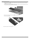
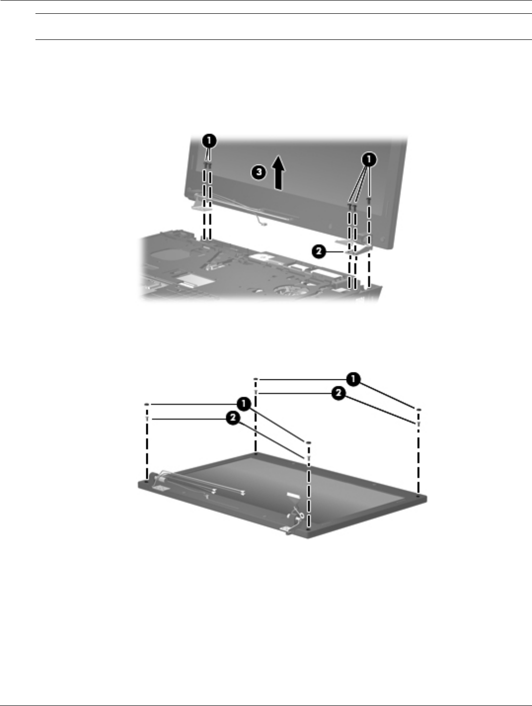
12. Remove the five Torx T8M2.5×6.0 screws 1 that secure the display assembly to the computer.
✎
The front-right screw on the right hinge secures a ground loop 2 that branches off of the display
panel cable.
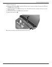
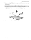
13. Lift the display assembly 3 straight up and remove it.
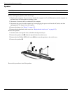
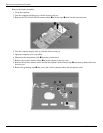
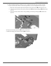
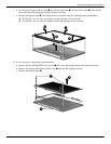
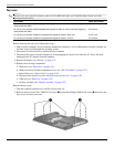
14. If it is necessary to replace the display bezel or any of the display assembly internal components:
a. Remove the four rubber screw covers 1 and the four Torx T8M2.5×6.0 screws 2 that secure the display
bezel to the display assembly.