


P/N 480-0005-00-15 2-25
Chapter 2: Hardware Components
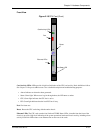
T1 WAN Card
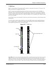
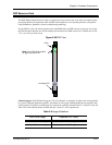
Each T1 card (see Figure 2-22) provides eight T1 span lines, a maximum of four cards (32 T1 spans or 768
DS0 voice channels) are supported in the system.
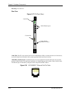
Each T1 card provides eight RJ-48 jacks on the rear of the card for connections to a line side (PBX) via
upstream T1 lines or to the trunk side (PSTN) via downstream T1 lines. Each T1 line provides 24 channels.
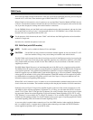
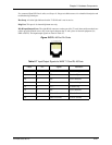
For each T1 interface, there are two types of signaling supported: Channel Associated Signaling (CAS) and
Common Channel Signaling (CCS). For T1 using CAS, channels 1-24 are available; for T1 using CCS, chan-
nels 1-23 are available.
For the CMS (14 slot), you can insert the T1 card in any one of the four left most slots (when facing the front
of the chassis).
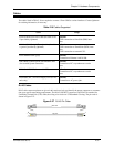
A crossover cable is required when connecting to a Line side (PBX) interface (when supplied by Quintum,
this is a red RJ-45 cable). A straight cable is required when connecting to the Trunk side (PSTN) interface
(when supplied by Quintum, this is a green RJ-45 cable).
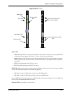
Figure 2-22 T1 WAN Card
Span LEDs. The T1 card contains eight Span Status LEDs, viewable from the front of the chassis, to provide
a high level indication of the system operational mode and chassis activity, including alarm activity. Each
LED relates to one line on the rear of the T1 WAN card. For example, Span Status 1 indicates the operational
activity of port 1 on the rear of the T1 WAN card. If all LEDs are lit green, the lines are operating properly.
TM
12
2
65
4
78
Span
Status
T1 WAN
HOT SWAP
Diag
T
ECHNOLOGIES, INC.
QUINTUM
TM
Front View
Rear View
RJ-48 Input/Output Ports
Span LEDs
Diag Port
Hot Swap LED
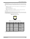
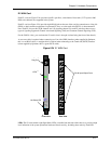
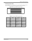
E1
Front View