


11
supports only the 1200 W AC supply, although the 6600 series is capable of supporting DC and other
common-slot supplies.
Two AC-to-12-V DC power supplies can be configured as 1+1 redundant supplies. The system is fully powered
with either power supply, and either power supply (but not both) can be removed and replaced while the
system is still racked, and the switch will continue to operate. Each power supply input is C14 with proper
safety ground.
110–120 VAC 200–240 VAC
Current < 7.5 A < 3.75 A
Output power > 548 W (> 45.7 A @ 12 VDC) > 548 W (> 45.7 A @ 12 VDC)
Efficiency (1 supply) < 677 W @ > 81% efficiency at full load < 677 W @ > 81% efficiency at full load
Efficiency (2 supplies) < 677 W @ > 75% efficiency at 50% load < 677 W @ > 75% efficiency at 50% load
Efficiency calculations include internal fans and line filter. The power supply size is 4.4 inch x 63 inch x 8 inch
(57 in
3
) with an output power density of ~9.6 W/in
3
. The power supply ships with two W40S12BUA5-01
40 mm x 40 mm x 28 mm (44,800 mm
3
) NIDEC fans or equivalent, producing 36 CFM (18 CFM each)
at .5 INWG using 13.2 W (6.6 W each).
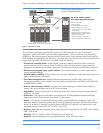
In terms of the power supply load-sharing algorithm when two supplies are installed, the power load is shared
equally across both supplies to improve longevity. All 6600 series products utilize the same power supply to
reduce sparing.
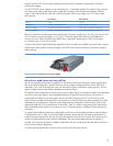
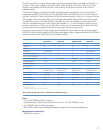
Figure 3: HP ProCurve 6600 Switch Power Supply (J9269A)
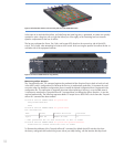
HP ProCurve 6600 Switch Fan Tray (J9271A)
The fan tray assembly contains the cooling fans for the interior of the 6600 chassis; the power supplies have
their own internal cooling fans. The 6600 fan tray consists of eight variable-speed fans, which offer N+N
redundancy. Thus, half of the eight fan rotors can fail and the system will maintain cooling capacity. The fan
speed is based on the sensed ambient temperature inside the chassis.
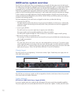
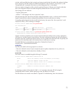
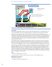
The default airflow configuration for the fan tray is power supply side to port side (front to back, also described
as power to port side). Figure 4 shows the default direction for the 6600 series products. The fan tray is
mechanically reversible, by first removing the fan tray and then loosening the four T10 torx screws on the
sides of the fan assembly. Reversing the fan tray should occur when the system has been powered off to allow
adequate time for replacement. A position sensor determines the configuration of the fan tray, which is then
reported through the CLI as to the direction of the airflow. There is a system configuration option (see section
titled “Monitoring airflow direction”) to report an error if a replacement fan is installed with the incorrect fan
orientation.
To support high-availability data center configurations, the fan tray can be replaced without system shutdown
if replacement occurs in under 3 minutes (the 6600 software monitors the time and takes required action to
protect the system). Because the fan tray can easily be replaced in less than 30 seconds, the 3-minute service
window provides adequate time to make a replacement, but users should replace the fans as quickly as
possible. Care must also be taken to install the replacement fan tray to help ensure that the airflow direction is
correct for the product’s deployment.
To reduce sparing requirements, all 6600 series products utilize the same fan tray.