


Cabling 96
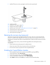
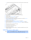
b.
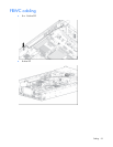
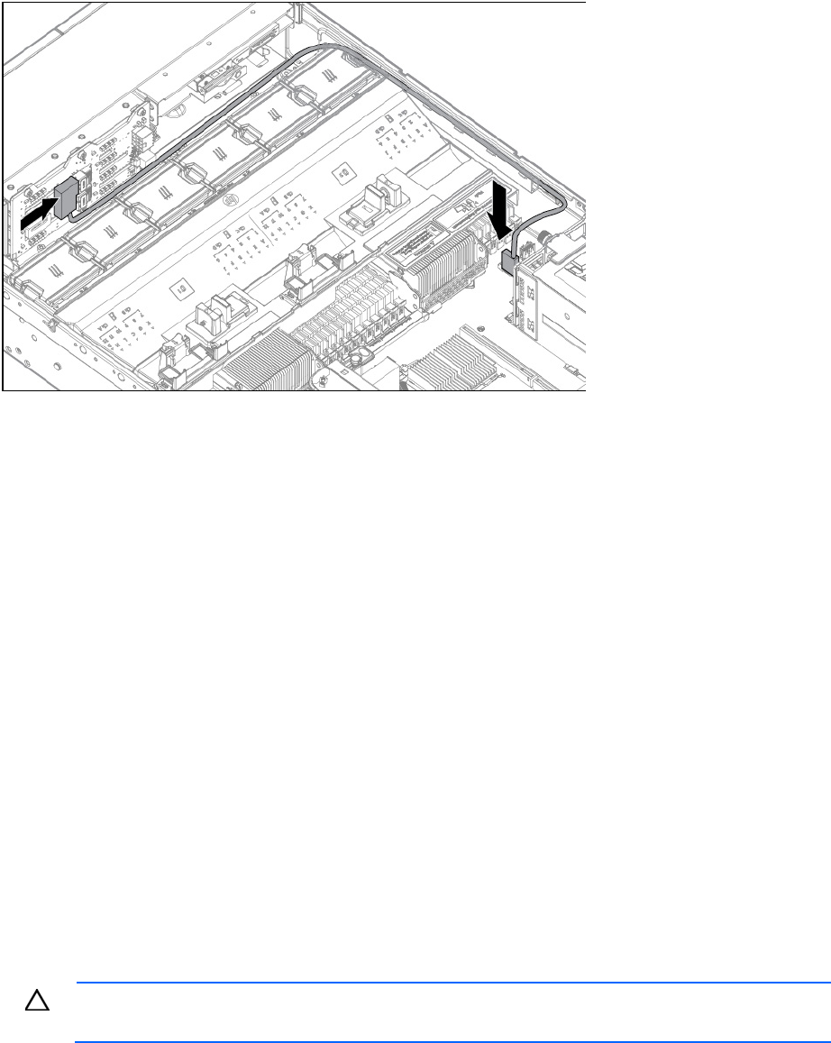
Connect the remaining chipset SATA cable connector to the SATA header on the hard drive cage.
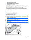
11. Coil the cables behind the hard drive backplane to minimize airflow impact.
12. Install the fan cage.
13. Install the air baffle ("Remove the air baffle" on page 32).
14. Install the PCI riser cage (on page 30), if removed.
15. Secure any full-length PCI expansion boards with the retaining latch on the air baffle ("Secure the
full-length expansion board retainer" on page 31).
16. Install the access panel (on page 25).
17. Install the server in the rack ("Installing the server into the rack" on page 38).
18. Remove any installed hard drives ("Removing a hot-plug SAS or SATA hard drive" on page 56).
19. Install a SATA hard drive ("Installing a hot-plug SAS or SATA hard drive" on page 55) in hard drive bay
5.
20. Install hard drive blanks in any empty hard drive bays.
21. Connect each power cord to the server.
22. Connect each power cord to the power source.
23. Power up the server (on page 23).
24. Using the HP ROM-Based Setup Utility (on page 103), disable the embedded HP Smart Array P420i
Controller, if necessary.
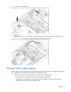
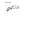
150W PCIe power cable option
CAUTION: To prevent damage to the server or expansion boards, power down the server and
remove all AC power cords before removing or installing the PCI expansion cage.