


iii
List of Figures
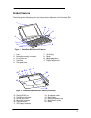
Figure 1 - OmniBook 800 External Features................................................................................3
Figure 2 - OmniBook 800 External Features (continued) .............................................................3
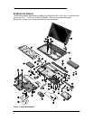
Figure 3 - Exploded Diagram.......................................................................................................4
Figure 4 - Main Diagnostic Screen...............................................................................................8
Figure 5 - Serial Loop Back Connector......................................................................................10
Figure 6 - Parallel Loop Back Connector ...................................................................................10
Figure 7 - SCSI Loop Back Connector.......................................................................................10
Figure 8 - SyCard Solder Bridges..............................................................................................11
Figure 9 - Sycard Test Results ..................................................................................................19
Figure 10 - Keyboard Test Screen.............................................................................................21
Figure 11 - Mouse Test Screen (text mode)...............................................................................23
Figure 12 - Mouse Test Screen (graphics mode) .......................................................................24
Figure 13 - Dock Keyboard Test Screen....................................................................................27
Figure 14 - DMI Components.....................................................................................................29
Figure 15 - Removing the Battery..............................................................................................50
Figure 16 - 8- and 16-MB Memory Modules...............................................................................51
Figure 17 - New and Old 32-MB Memory Module (respectively) ................................................51
Figure 18 - Removing the Memory Module................................................................................52
Figure 19 - Hard Drive Screws...................................................................................................53
Figure 20 - Folding the Keyboard Open.....................................................................................54
Figure 21 - Hard Drive Removal................................................................................................54
Figure 22 - Hard Drive Removal (continued) .............................................................................55
Figure 23 - Hard Drive Insulator Flap.........................................................................................55
Figure 24 - Inserting the Hard Drive...........................................................................................56
Figure 25 - Proper Keyboard Flex Cable Position......................................................................56
Figure 26 - IBM and Toshiba Hard Drive Breather Holes (respectively) .....................................57
Figure 27 - Removing the Mouse...............................................................................................58
Figure 28 - Keyboard Screws.....................................................................................................60
Figure 29 - Folding the Keyboard Open.....................................................................................60
Figure 30 - Keyboard Flex Cables .............................................................................................61
Figure 31 - Keyboard Flex Cable Placement .............................................................................61
Figure 32 - Bottom Case Screws and Rubber Feet....................................................................62
Figure 33 - Keyboard Support Plate Screws ..............................................................................63
Figure 34 - Display Flex Cables.................................................................................................64
Figure 35 - Top Case and Display Removal ..............................................................................65
Figure 36 - Intel Inside Sticker Placement .................................................................................66
Figure 37 - Removing the CPU..................................................................................................67
Figure 38 - Heat Transfer Disk and Keyboard Support Insulator ................................................68
Figure 39 - CPU Thermal Coupling............................................................................................68
Figure 40 - Logic PCA Removal................................................................................................71
Figure 41 - Grommet and Bushing Placement...........................................................................72
Figure 42 - Paw Active Removal ...............................................................................................73