


67
CPU
(HP Authorized Service Providers Only)
Required Equipment
• Torx #6 screwdriver
Removal Procedure
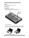
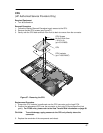
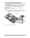
1. Follow the Display Removal Procedure to gain access to the CPU.
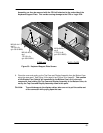
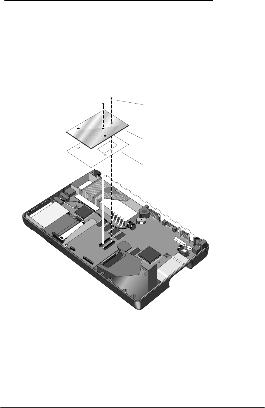
2. Remove the two CPU screws (see Figure 37).
3. Gently rock the CPU back and forth from front to back to remove from the connector.
Replacement Procedure
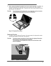
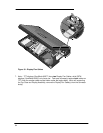
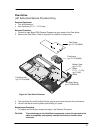
1. Ensure the CPU Insulator is positioned over the CPU connector on the Logic PCA.
2. Position the replacement CPU over the connector on the Logic PCA and press firmly but
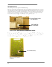
gently. For F1360 units, please refer to the Heat Transfer Disk information on page 68.
CAUTION:
To avoid damage, apply pressure to the CPU only directly above the
connector.
3. Replace the remainder of the components and reboot.
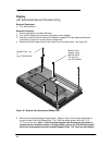
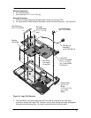
Figure 37 - Removing the CPU
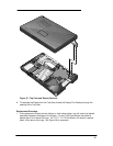
CPU Screws
M1.6x0.35x4.0mm
1.0-2.0 in-lb
(p/n 0515-2852)
CPU Insulator
(p/n F1360-20007)
CPU